
Eureka
For R&D, Eureka makes reading and utilizing patents & technical documents easy.
Eureka AIR
Designed for self-driven R&D workflows. Generate viable solutions, solve complex R&D challenges, empower your innovation with AI.

Eureka Materials
Designed for material experts only. Revolutionize your material R&D, from search, analyze, to developing new materials.

TechResearch
Generate reliable direction feasibility study reports for your R&D in just a few steps.

TechSeek
Discover and master advanced knowledge NOW. Basics, ideas, possibilities, all at once.

TechMind
As an expert in R&D Theories, TechMind can generates customized viable solutions instantly.

TechRisk
Analyze your overall solution with one click, know your potential R&D risks in advance.

TechMonitor
Get weekly tech updates, stay abreast of the latest tech innovations and key insights.
Pointing element, display system, and method of controlling pointing element
- Summary
- Abstract
- Description
- Claims
- Application Information
AI Technical Summary
Benefits of technology
Problems solved by technology
Method used
Image

Examples
first embodiment
A7. Conclusion of First Embodiment
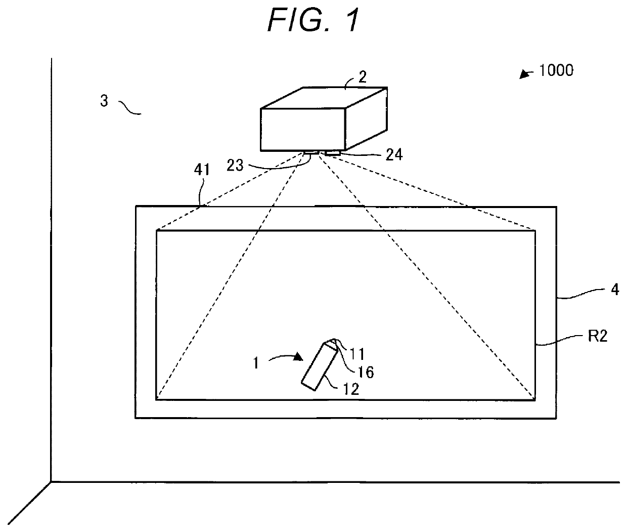
[0134]The pointing element 1, the display system 1000, and the operation method according to the present embodiment described above include the following aspects.
[0135]The pressing part 15 presses the opposed part 14 against the pressure sensor 13 irrespective of presence or absence of the pressure to the tip part 11, and changes the pressing force for pressing the opposed part 14 against the pressure sensor 13 in accordance with the pressure to the tip part 11. The signal generation section 17 receives the first signal having a level based on the pressing force from the pressure sensor 13, and then generates the second signal by changing the level of the first signal. The light emitting part 16 outputs the information based on the second signal to the outside of the pointing element 1.
[0136]According to this aspect, the pressing part 15 presses the opposed part 14 against the pressure sensor 13 irrespective of presence or absence of the pressure to...
first modified example
B1. First Modified Example
[0145]In the first embodiment, the output of the information based on the second signal Vout is not limited to the output using the light emission pattern in the light emitting part 16.
[0146]For example, it is possible for the pointing element 1 to transmit the information based on the pressure to the tip part 11 as an example of the information based on the second signal Vout with a communication section for executing the communication using the Near Field Communication method, and it is possible for the projector 2 to receive the information based on the pressure to the tip part 11 with a communication section for executing the communication using the Near Field Communication method. In this case, the communication section provided to the pointing element 1 becomes another example of the output section. As examples of the Near Field Communication method, there can be cited Bluetooth and Wi-Fi. Bluetooth is a registered trademark. Wi-Fi is a registered tra...
second modified example
B2. Second Modified Example
[0147]In the first embodiment and the first modified example, the adjustment signal is not limited to the PWM signal, but can also be, for example, a signal representing the second adjustment voltage Vadj(target). In this case, the lowpass filter 171a can be omitted.
PUM
 Abstract
Description
Claims
Application Information
 - R&D Engineer
- R&D Manager
- IP Professional
- Industry Leading Data Capabilities
- Powerful AI technology
- Patent DNA Extraction
Browse by: Latest US Patents, China's latest patents, Technical Efficacy Thesaurus, Application Domain, Technology Topic, Popular Technical Reports.
© 2024 PatSnap. All rights reserved.Legal|Privacy policy|Modern Slavery Act Transparency Statement|Sitemap|About US| Contact US: help@patsnap.com