Supercharge Your Innovation With Domain-Expert AI Agents!

Chuck table, cutting apparatus, and method correcting chuck table

a technology of chuck table and cutting device, which is applied in the direction of electrical equipment, manufacturing tools, and semiconductor devices. it can solve the problems of workpieces prone to chipping and the suction plate cannot support the workpi

Active Publication Date: 2021-08-24
DISCO CORP
View PDF6 Cites 0 Cited by
  • Summary
  • Abstract
  • Description
  • Claims
  • Application Information

AI Technical Summary

Benefits of technology

The solution effectively prevents chipping and corner cracks by ensuring the workpiece is securely held through adhesive tape and suction, maintaining contact with a flat surface free of pores, thus enhancing cutting precision and reducing damage.

Problems solved by technology

However, while the suction plate of porous ceramics can apply attractive suction forces to the entire surface of the workpiece, since the suction plate has minute pores throughout its entire surface, the suction plate is unable to support the workpiece at positions corresponding to the pores, and the workpiece tends to develop chippings at the positions corresponding to the pores.

Method used


Image

  • Chuck table, cutting apparatus, and method correcting chuck table
  • Chuck table, cutting apparatus, and method correcting chuck table
  • Chuck table, cutting apparatus, and method correcting chuck table

Examples


Embodiment Construction

[0035]Preferred embodiments of the present invention will hereinafter be described in detail with reference to the drawings. The present invention is not limited by the details of the embodiments described below. The components described below cover those which could easily be envisaged by those skilled in the art and those which are essentially identical to those described above. Furthermore, the arrangements described below can be combined in appropriate manners. Various omissions, replacements, or changes of the arrangements may be made without departing from the scope of the present invention.

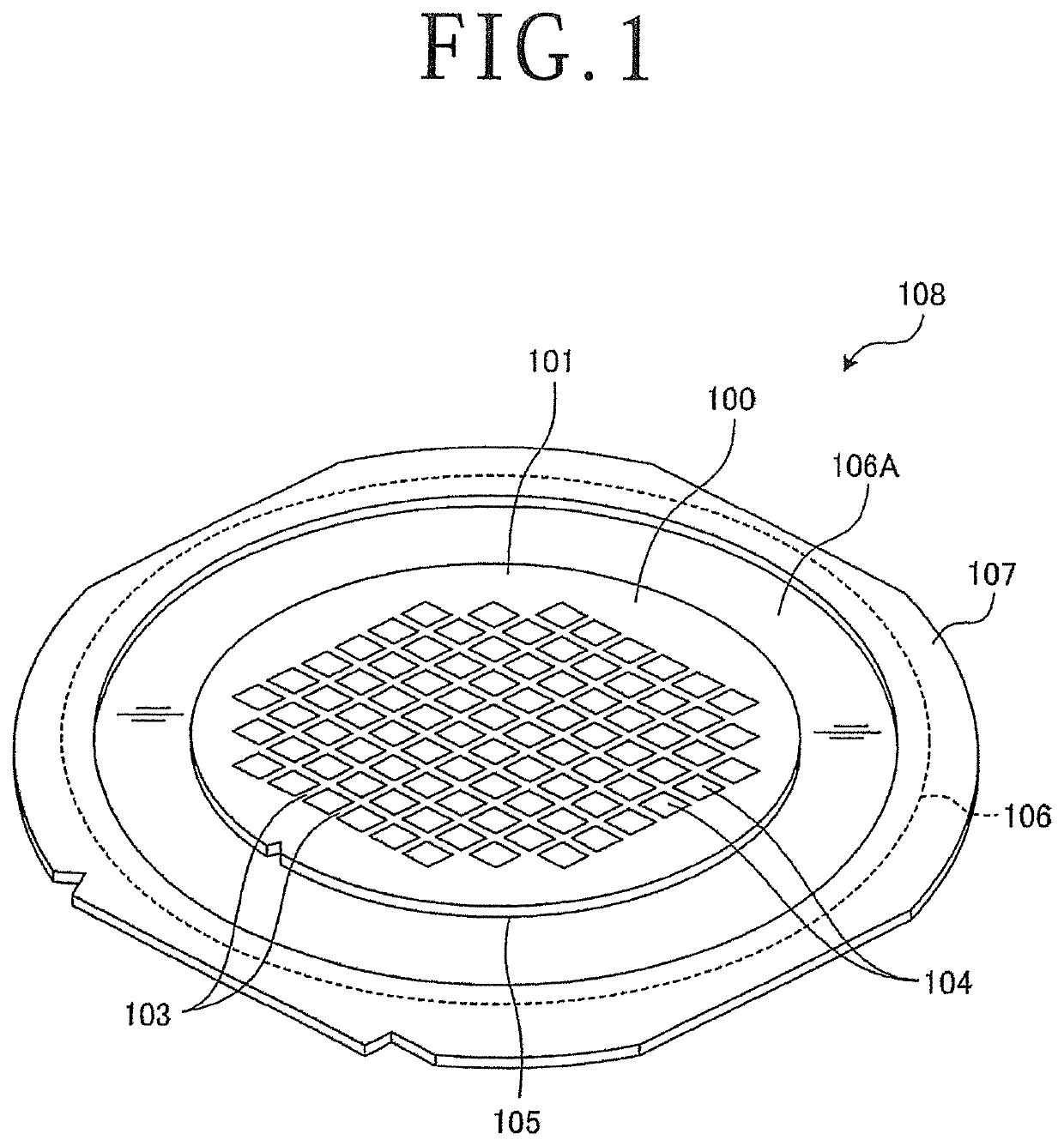
[0036]FIG. 1 is a perspective view of a frame unit including a workpiece to be processed by a cutting apparatus according to an embodiment of the present invention.

[0037]As illustrated in FIG. 1, a workpiece, denoted by 100, is a disk-shaped semiconductor wafer or optical device wafer including a substrate 101 made of silicon, sapphire, gallium, or the like. The workpiece 100 has a pluralit...


PUM


Abstract

A chuck table includes a main part having a holding surface for holding thereon a workpiece through a dicing tape, and a frame holder disposed around the main part for holding the annular frame. The main part has a flat surface that functions as the holding surface, an outer circumferential suction groove defined in a region of the holding surface that underlies an annular region of the adhesive tape between the workpiece and the frame of the frame unit, for holding the annular region of the adhesive tape under suction, and a suction channel held in fluid communication with the outer circumferential suction groove and a suction source. The frame holder pulls down the frame to a position lower than the holding surface to hold the dicing tape in close contact with the holding surface.

Description

BACKGROUND OF THE INVENTIONField of the Invention[0001]The present invention relates to a chuck table, a cutting apparatus, and a method of correcting a chuck table.Description of the Related Art[0002]Generally, there are known dicing saws, i.e., cutting apparatus, for cutting a wafer on which various devices such as semiconductor devices, optical devices, SAW filter devices, etc. are formed thereon, or a workpiece of ceramics or glass, or a packaged device, into individual device chips. A cutting apparatus cuts a workpiece that is fixed to a chuck table by a dicing tape with a cutting blade. It is known in the art to be able to prevent the workpiece from developing chippings especially on its reverse side and cracks at corners thereof by firmly securing the workpiece to the chuck table against vibrations while cutting the workpiece. In order to apply attractive suction forces to the entire surface of the workpiece, a suction plate of porous ceramics is used on the chuck table for a...

Claims


Application Information

Patent Timeline
Patent Type & Authority Patents(United States)
IPC IPC(8): H01L21/683H01L21/67B25B11/00
CPCH01L21/6838B25B11/005H01L21/67092H01L21/6836H01L2221/68327H01L21/68714
Inventor YAMAMOTO, SETSUOSEKIYA, KAZUMA
Owner DISCO CORP
Features
  • R&D
  • Intellectual Property
  • Life Sciences
  • Materials
  • Tech Scout
  • Unparalleled Data Quality
  • Higher Quality Content
  • 60% Fewer Hallucinations
Learn More