Method and apparatus for manufacturing a three-dimensional object

Active Publication Date: 2021-09-07
EOS ELECTRO OPTICAL SYST
View PDF23 Cites 0 Cited by
  • Summary
  • Abstract
  • Description
  • Claims
  • Application Information

AI Technical Summary

Benefits of technology

[0006]An object of the present invention consists in providing an improved method or, respectively, an improved apparatus for manufacturing a three-dimensional object by a layer-by-layer application and selective solidification of a building material.

Problems solved by technology

Generated splashes, smoke, and condensates as well as released gaseous or solid substances can lead to contaminations of the apparatus.
Furthermore, generated splashes, smoke, and condensates as well as r

Method used


Image

  • Method and apparatus for manufacturing a three-dimensional object
  • Method and apparatus for manufacturing a three-dimensional object
  • Method and apparatus for manufacturing a three-dimensional object

Examples


Example

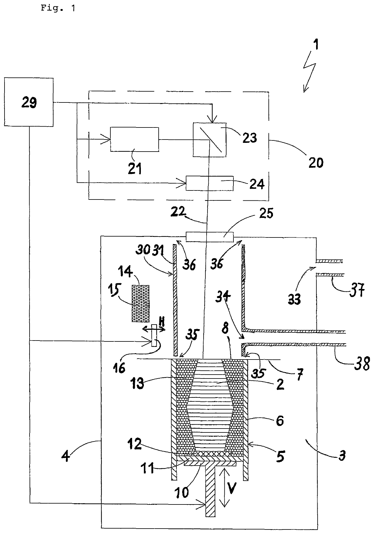
[0035]The apparatus shown in FIG. 1 is a laser sintering or laser melting apparatus 1 for manufacturing an object 2.

[0036]The laser sintering or laser melting apparatus 1 contains a process chamber 3 having a chamber wall 4. In the process chamber 3 a container 5 open to the top and having a wall 6 is arranged. In the container 5 a support 10 movable in a vertical direction V is arranged at which a base plate 11 is mounted which closes the container 5 in a downward direction and thereby forms its bottom. The base plate 11 may be a plate formed separately from the support 10, which is attached to the support 10, or it may be integrally formed with the support 10. Depending on a powder used and a process, a building platform 12 on which the object 2 is built up may further be mounted on the base plate 11. However, the object 2 may also be built up on the base plate 11 itself, which then serves as a building platform.

[0037]In FIG. 1, the object to be built in the container 5 on the bui...


PUM

PropertyMeasurementUnit
Pressureaaaaaaaaaa
Areaaaaaaaaaaa

Abstract

A method of manufacturing a three-dimensional object by a layer-by-layer application and selective solidification of a building material by exposure to a radiation. A hollow body is arranged in a process chamber above a build area which hollow body substantially extends from the build area in a direction of an upper side of the wall of the process chamber. Gas is supplied to the process chamber in such a manner and gas is discharged from the process chamber in such a manner that a lower pressure exists in the region of the process chamber lying within the hollow body than in the region of the process chamber lying outside the hollow body.

Description

TECHNICAL FIELD OF THE INVENTION[0001]The present invention relates to a method and an apparatus for manufacturing a three-dimensional object by a layer-by-layer application and selective solidification of a building material.BACKGROUND OF THE INVENTION[0002]Methods and apparatuses of this type are, for instance, used in Rapid Prototyping, Rapid Tooling, and Additive Manufacturing. An example of such a method is known as “selective laser sintering” or “selective laser melting”. In the course of this, a thin layer of a building material in powder form is repeatedly applied to a build area, and the building material in each layer is selectively solidified by selectively irradiating it using a laser beam, i.e. the building material is partially or completely melted at these points and solidifies thus forming a material bond. In this sense, a solidification point is a position subjected to this process, i.e. at which the partial or complete melting is (currently) performed.[0003]Documen...

Claims


Application Information

Patent Timeline
IPC IPC(8): B33Y10/00B33Y50/02B29C64/153B29C64/25B23K26/12B23K26/342B29C64/364B29C64/393B28B1/00B22F10/10B22F12/00B33Y30/00B28B17/00
CPCB22F12/00B23K26/1224B23K26/342B28B1/001B28B17/0081B29C64/153B29C64/25B29C64/364B29C64/393B33Y10/00B33Y30/00B33Y50/02B22F10/10B22F2201/20B22F2999/00Y02P10/25B22F10/28B22F10/32B22F12/70B22F2203/13
Inventor BAUMANN, ANDREAS
Owner EOS ELECTRO OPTICAL SYST
Why Eureka
Try Eureka