Temperature control apparatus for humidity sensor

Inactive Publication Date: 2003-06-26
HONDA MOTOR CO LTD
View PDF14 Cites 7 Cited by
  • Summary
  • Abstract
  • Description
  • Claims
  • Application Information

AI Technical Summary

Benefits of technology

[0008] The present invention has been made to solve the problem mentioned above, and it is an object of the invention to provide a temperature control apparatus for a humidity sensor which is capable of preventing impurities from sticking on a sensor element, while protecting the sensor element from cracking due to the humidity sensor heated by a heater in the presence of condensation, to maintain a high accuracy of detection by the humidity sensor.
[0010] According to this temperature control apparatus for a humidity sensor, the sensor element is heated by the heater to bring the actual temperature of the sensor element of the humidity sensor to the first predetermined temperature during an operation of the internal combustion engine. Since the sensor element is thus maintained at a high temperature during the operation of the internal combustion engine, impurities in exhaust gases can be prevented from sticking on the sensor element. It is therefore possible to maintain a high detection accuracy of the humidity sensor.
[0012] According to this preferred embodiment of the temperature control apparatus for a humidity sensor, since the heater control means controls the amount of power supplied to the heater in a feedback manner to bring the actual temperature of the sensor element to the first predetermined temperature, impurities in exhaust gases can be prevented from sticking on the sensor element, while minimizing the power consumed by the heater. In addition, it is possible to maintain a high detection accuracy of the humidity sensor.
[0014] According to this preferred embodiment of the temperature control apparatus for a humidity sensor, the heater control means controls the heater with a smaller heating amount when the temperature of the sensor element is brought to the first predetermined temperature than when the temperature of the sensor element is lower than a second predetermined temperature. With this meticulous control, the temperature of the sensor element slowly rises at low temperatures at which the sensor may element suffer from condensation, so that the condensation can be eliminated with minimum power consumption while ensuring the prevention of the sensor element from cracking due to a sudden change in temperature.
[0016] According to this preferred embodiment of the temperature control apparatus for a humidity sensor, the heater control means control the heater to bring the temperature of the sensor element to a fourth predetermined temperature lower than the second predetermined temperature or lower while the characteristic change parameter calculating means is calculating the characteristic change parameter. Thus, the humidity sensor can detect the humidity with the sensor element being controlled at a temperature at which the sensor element exactly presents a change in the characteristic thereof. As such, the characteristic change parameter can be properly calculated based on the detected humidity.
[0018] According to this preferred embodiment of the temperature control apparatus for a humidity sensor, the heater control means controls the heater to converge the temperature of the sensor element to a third temperature higher than the first predetermined temperature or higher when the calculated characteristic change parameter is larger than a predetermined value. Thus, when the humidity sensor presents a large change in the characteristic due to impurities in exhaust gases which stick on the sensor element, the impurities can be removed at the higher third predetermined temperature, thereby making it possible to recover the original characteristic of the humidity sensor and hence the detection accuracy of the humidity sensor.

Problems solved by technology

As a result, the adsorbent is deteriorated, possibly causing a gradual degradation in the ability of the adsorbent to adsorb the hydrocarbons.
In this way, the humidity is detected with the sensor element exposed to exhaust gases, so that impurities such as water droplets produced by condensation, unburnt fuel components included in the exhaust gases, and the like can stick to the sensor element, in which case the humidity sensor fails to correctly detect the humidity of exhaust gases, resulting in the inability to correctly detect a deterioration of the adsorbent.
However, during a normal operation of the internal combustion engine, impurities other than water droplets within exhaust gases may also stick to the sensor element.
However, the heat cleaning is not performed when it is not assumed that the sensor element experiences condensation even if such impurities stick on the sensor element, resulting in a degraded accuracy of detection by the humidity sensor.
In addition, since the heater is merely operated for a predetermined time period, the heat cleaning control may fail to sufficiently remove impurities or operate the heater for useless depending on, for example, a temperature state of an exhaust system and the like.
Moreover, since the sensor element is suddenly heated by the heater in the presence of condensation, a sudden increase in the temperature of the sensor element from a low temperature, resulting from the heating, would possibly cause cracking of the sensor element.

Method used


Image

  • Temperature control apparatus for humidity sensor
  • Temperature control apparatus for humidity sensor
  • Temperature control apparatus for humidity sensor

Examples


Embodiment Construction

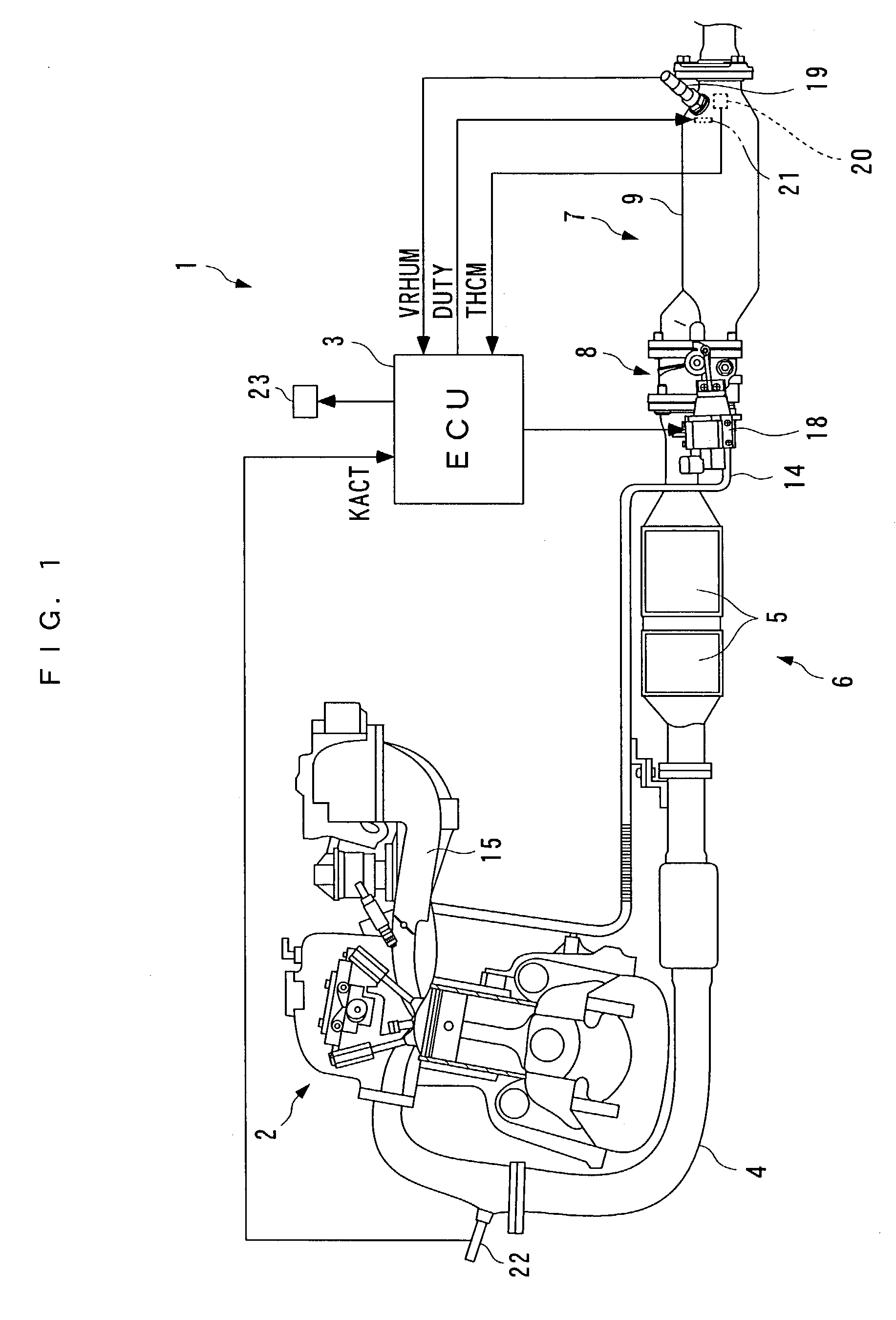
[0031] In the following, a preferred embodiment of the present invention will be described in detail with reference to the accompanying drawings. FIG. 1 illustrates an internal combustion engine (hereinafter called the "engine") 2 which employs a temperature control apparatus for a humidity sensor 1 (hereinafter simply called the "control apparatus") according to one embodiment of the present invention. As illustrated in FIG. 1, the control apparatus 1 comprises an ECU 3 (which implements a heater control means and a characteristic change parameter calculating means) which executes control processing, later described.

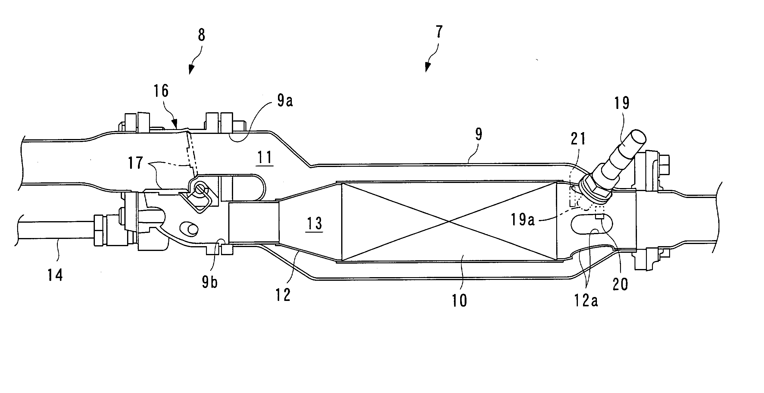
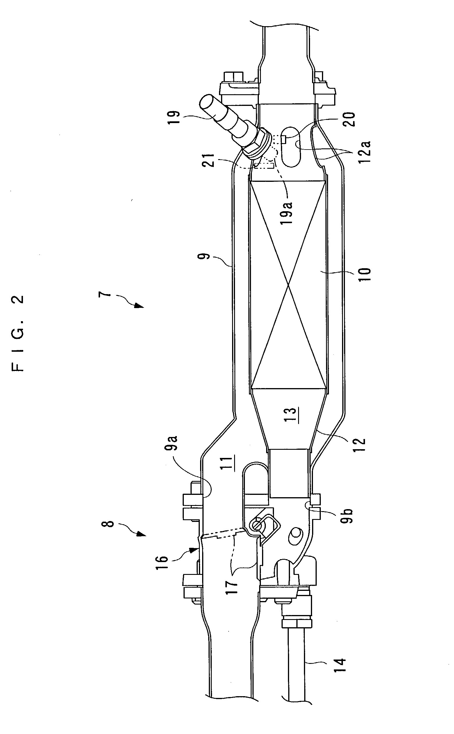
[0032] A catalyzer 6 having two three-way catalysts 5, and a hydrocarbon adsorber 7 for adsorbing hydrocarbons are provided in this order from the upstream side, halfway in an exhaust pipe (exhaust passage) 4 of the engine 2 for purifying exhaust gases. The two three-way catalysts 5 of the catalyzer 6 are arranged adjacent to each other along the exhaust pipe 4, and pur...


PUM


Abstract

A temperature control apparatus for a humidity sensor is provided for preventing impurities from sticking on a sensor element, while protecting the sensor element from cracking due to the humidity sensor heated by a heater in the presence of condensation, to maintain a high detection accuracy of the humidity sensor. The temperature control apparatus is configured to control the temperature of a sensor element of a humidity sensor disposed in an exhaust passage of an internal combustion engine for detecting the humidity within the exhaust passage. The temperature control apparatus comprises a heater for heating the sensor element, a temperature sensor for detecting the temperature of the sensor element, and an ECU for controlling a heating amount of the heater to bring the detected temperature of the sensor element to a first predetermined temperature during an operation of the internal combustion engine.

Description

[0001] 1. Field of the Invention[0002] The present invention relates to a temperature control apparatus for controlling the temperature of a sensor element of a humidity sensor disposed in an exhaust passage of an internal combustion engine for detecting the humidity within the exhaust passage in order to maintain a good condition for the sensor element.[0003] 2. Description of the Prior Art[0004] Some internal combustion engines are provided with an adsorbent in its exhaust system for adsorbing hydrocarbons in exhaust gases upon starting. The adsorbent has, for example, zeolite on the surface such that hydrocarbons in exhaust gases introduce into pores of zeolite when they pass through the adsorbent, and are adsorbed by the adsorbent. The adsorbent desorbs the hydrocarbons once adsorbed thereby when the adsorbent is heated by exhaust gases to a predetermined temperature or higher (for example, 100-250.degree. C.), permitting the desorbed hydrocarbons to be recirculated to the inter...

Claims


Application Information

Patent Timeline
IPC IPC(8): G01K7/16F01N3/00F01N3/08F01N13/02F02D41/14F02D45/00G01N27/04G01N27/12
CPCF01N3/0814F01N3/0835F01N3/0878F01N3/101F02D41/1456F01N13/009G01N27/121Y02T10/22F01N13/0097F01N13/0093F02D41/1494Y02T10/12
Inventor UENO, MASAKIMACHIDA, KEIENDO, TETSUOYAMAZAKI, HIDEHARU
Owner HONDA MOTOR CO LTD
Why Eureka
Try Eureka