Light source apparatus, image projection apparatus, and control apparatus that control multiple light sources at different lighting timings

a technology of image projection and control apparatus, which is applied in the direction of projectors, projectors, and picture reproducers using projection devices, etc., can solve the problems of long startup time of projectors, catastrophic optical damage, and optical damage, and achieve the effect of shortening the startup tim

Active Publication Date: 2021-09-07
CANON KK
View PDF23 Cites 1 Cited by
  • Summary
  • Abstract
  • Description
  • Claims
  • Application Information

AI Technical Summary

Benefits of technology

[0005]The present invention provides a light source apparatus and an image projection apparatus, each of which can shorten a startup time while suppressing the COD in a light source, such as a red LD.

Problems solved by technology

The red LD characteristically it is more likely to cause an optical damage (COD: Catastrophic Optical Damage) particularly when the temperature is low than the blue LD.
Nevertheless, the method disclosed in JP 2016-131219 takes a time to complete turning on the LD in order to control the drive current supplied to the LD, and consequently makes longer the startup time of the projector.

Method used


Image

  • Light source apparatus, image projection apparatus, and control apparatus that control multiple light sources at different lighting timings
  • Light source apparatus, image projection apparatus, and control apparatus that control multiple light sources at different lighting timings
  • Light source apparatus, image projection apparatus, and control apparatus that control multiple light sources at different lighting timings

Examples


first embodiment

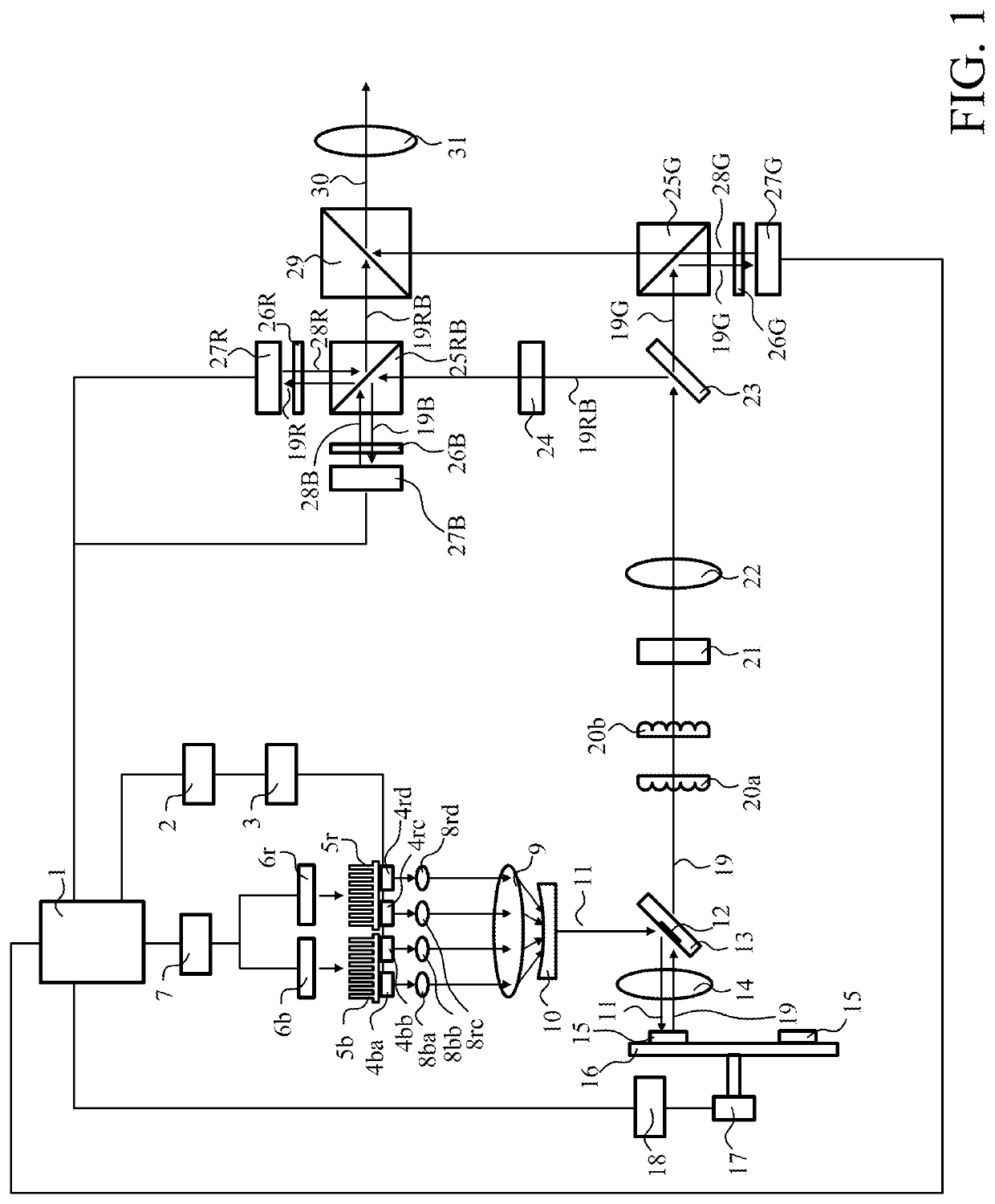
[0019]FIG. 1 illustrates a configuration of a projector as an image projection apparatus according to a first embodiment of the present invention. In the following description, R, G, and B respectively mean red, green, and blue. Reference numeral 1 denotes a system controller, reference numeral 2 denotes a drive current calculator, and reference numeral 3 denotes a light source driver. Reference numerals 4ba and 4bb denote B light sources, and reference numerals 4rc and 4rd denote R light sources. Reference numeral 5b denotes a B light source heat sink (heat sink for the B light source), reference numeral 5r denotes an R light source heat sink (heat sink for the R light source), reference numeral 6b denotes a B light source cooler (cooler for the B light source), reference numeral 6r denotes an R light source cooler (cooler for the R light source), and reference numeral 7 denotes a cooling controller.

[0020]Reference numerals 8ba and 8bb denote B collimator lenses, and reference nume...

second embodiment

[0052]Referring now to FIG. 4, a description will be given of a second embodiment according to the present invention. This embodiment stepwise increases the drive currents supplied to the R light sources 4rc and 4rd.

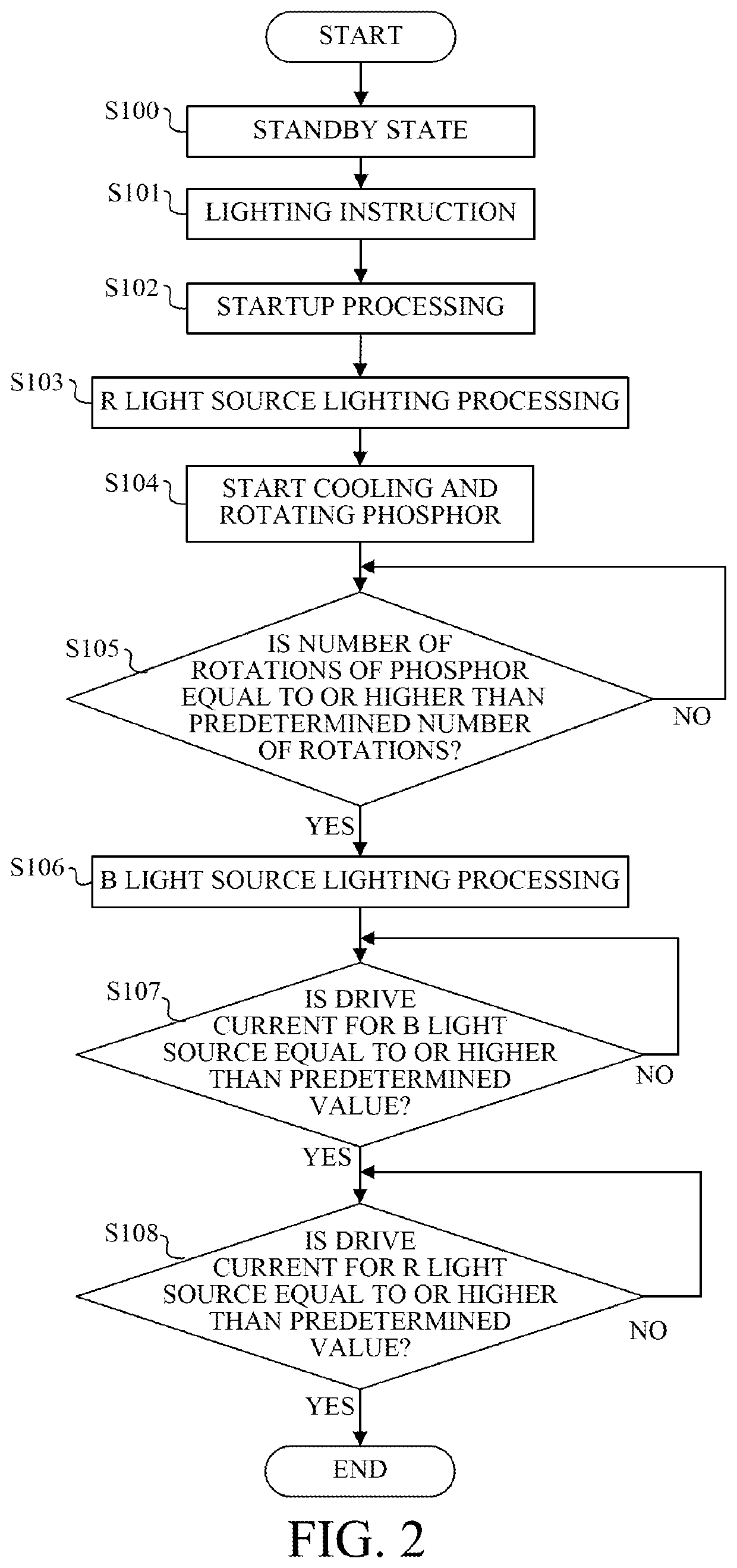
[0053]In a flowchart of FIG. 4, processing of the steps S100 to S102 and the steps S104 to S108 are the same as the processing of the steps S100 to S102 and the steps S104 to S108 according to the first embodiment (FIG. 2). This embodiment performs processing of the step S201 instead of the step S103 in the first embodiment (FIG. 2).

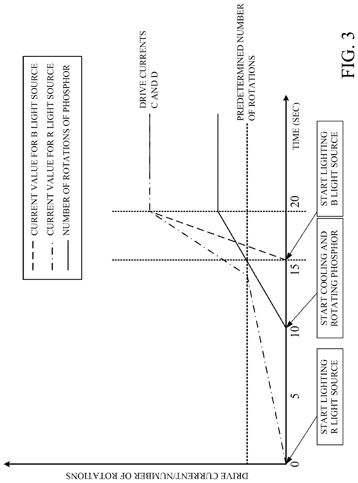
[0054]In the step S201, the system controller 1 instructs the drive current calculator 2 to calculate the drive currents for lighting the R light sources 4rc and 4rd, and instructs the light source driver 3 to supply the drive currents to the R light sources 4rc and 4rd. The drive current calculator 2 stepwise increases the drive currents supplied to the R light sources 4rc and 4rd from 0 to a predetermined current C corresponding to the pre...

third embodiment

[0056]Next follows a description of a third embodiment according to the present invention. FIG. 5 illustrates a configuration of a projector according to this embodiment. Among components illustrated in FIG. 5, components common to those of the first embodiment (FIG. 1) will be designated by the same reference numerals as those of the first embodiment, and a description thereof will be omitted.

[0057]The projector according to this embodiment includes a phosphor cooler 40. The phosphor cooler 40 includes a cooling fan for cooling the phosphor 15 (the phosphor cooler will be referred to as a phosphor cooling fan hereinafter). The phosphor cooling fan 40 cools the phosphor 15 by cooling the phosphor support member 16. The system controller 1 can control the temperature of the phosphor 15 by controlling the number of rotations of the phosphor cold fan 40 through the cooling controller 7.

[0058]A flowchart in FIG. 6 illustrates lighting startup processing of the B light sources 4ba and 4b...


PUM


Abstract

A light source apparatus includes a first light source, a second light source configured to emit light with a different wavelength than that of the first light source; and a controller for controlling each of the first and second light sources. The controller provides a control such that the second light source takes a longer time from a lighting start to a lighting completion than the first light source, and the second light source starts lighting earlier than the first light source.

Description

BACKGROUND OF THE INVENTIONField of the Invention[0001]The present invention relates to a light source apparatus suitable for an image projection apparatus, such as a liquid crystal projector.Description of the Related Art[0002]Some of image projection apparatuses (referred to as projectors hereinafter) that modulate light emitted from a light source with a light modulation element, such as a liquid crystal panel, and project the light onto a projection surface use a laser diode (LD) as a light source. As disclosed in Japanese Patent Laid-Open No. (“JP”) 2016-224304, some of these projectors uses a plurality of LDs (blue LD and red LD) that emit light fluxes with different wavelengths.[0003]The red LD characteristically it is more likely to cause an optical damage (COD: Catastrophic Optical Damage) particularly when the temperature is low than the blue LD. JP 2016-131219 discloses a method for suppressing the COD.[0004]Nevertheless, the method disclosed in JP 2016-131219 takes a tim...

Claims


Application Information

Patent Timeline
Patent Type & Authority Patents(United States)
IPC IPC(8): G03B21/20G03B21/16H04N9/31G03B21/00
CPCG03B21/2053G03B21/16G03B21/204G03B21/006G03B21/2013G03B21/2073
Inventor HOSHINO, KIMIYA
Owner CANON KK
Why Eureka
Try Eureka