Determination of a spatial orientation

a spatial orientation and determination technology, applied in the field of spatial orientation determination, can solve the problems of inexpensive gyroscopes subject to certain measuring inaccuracy, and achieve the effect of improving the realistic impression of information presented and increasing the accuracy of the determined spatial orientation

Active Publication Date: 2021-09-07
ROBERT BOSCH GMBH
View PDF14 Cites 0 Cited by
  • Summary
  • Abstract
  • Description
  • Claims
  • Application Information

AI Technical Summary

Benefits of technology

[0007]By use of the described method, in particular a long-term drift or a measuring error of the first sensor may be compensated for in an improved manner. The spatial orientation in space may thus be determined quickly and accurately. The use of a low pass filter for smoothing measured acceleration values may be avoided. The spatial orientation determined with the aid of the method may thus be present with reduced latency. The method is particularly suited for use on a VR device, which requires a low-latency and accurate information concerning the rotatory orientation in order to produce a convincing VR effect.
[0008]The method is preferably run through iteratively, in that in each pass of the method, the corrected estimated value for the spatial orientation of the object from the preceding pass is taken as the starting value for the spatial orientation. When used in conjunction with a VR device, the method may be carried out at a frequency of several 1000 Hz, for example. By feedback of the determined orientation into the orientation determination of a subsequent pass, an overall improved accuracy of the determined orientation may be achieved.
[0015]In addition, it is preferred that one of the sensors is encompassed by a micromechanical system. The micromechanical system (also microelectromechanical system or micromachine) is generally designed with semiconductor technology, and uses components whose smallest dimensions are typically in the micron range. Such a sensor generally includes a micromechanical test mass that is movably suspended, sensors for sampling the movement of the test mass, and an evaluation circuit for determining the desired variable based on the determined movement. Such sensors may be cost-efficient. Measurement inaccuracies or a long-term drift of such a sensor may be better compensated for by the described processing.
[0017]A VR device includes a fastening device fastening to the head of a user, a visual or acoustic output device, and the above-described device. In this way, an adaptation of stimuli to a determined spatial orientation with the aid of the visual or acoustic output device may be carried out in an improved manner. The user may thus form a greatly improved realistic impression of the information presented.
[0018]In another preferred specific embodiment, the fastening device is adjustable, and a sampling device is provided for determining the distance of the second sensor from the rotational axis, based on an adjustment state of the fastening device. The method may thus be automatically adapted to different head sizes of various users in an improved manner. The accuracy of the determined spatial orientation may thus be increased.

Problems solved by technology

However, in particular inexpensive gyroscopes are subject to a certain measuring inaccuracy.

Method used


Image

  • Determination of a spatial orientation
  • Determination of a spatial orientation
  • Determination of a spatial orientation

Examples


Embodiment Construction

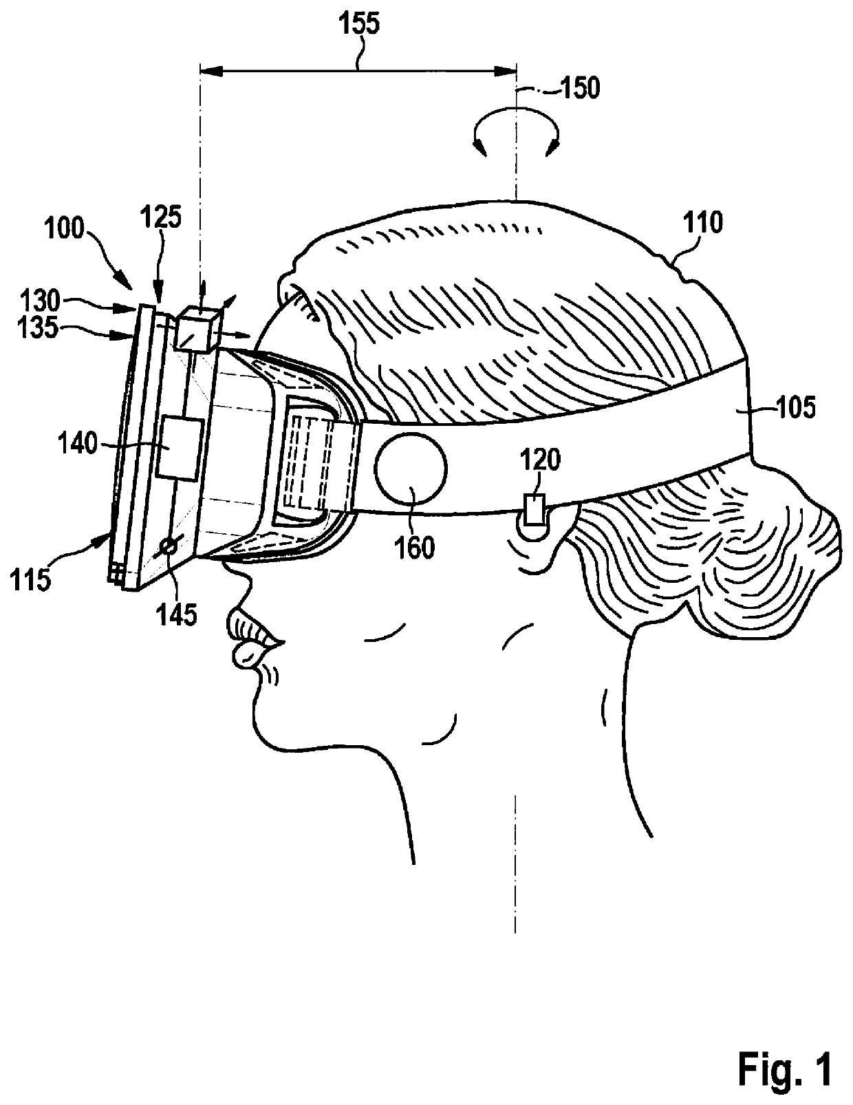
[0022]FIG. 1 shows a VR device 100 that is mounted on the head of a user 110 with the aid of a fastening device 105. The VR device preferably includes a visual output device 115 and / or an acoustic output device 120. With the aid of output devices 115, 120, stimuli may be presented to user 110 that give him / her the impression of a generated, i.e., virtual, reality. For this purpose, the stimuli are to be controlled as a function of a spatial orientation of the head of user 110.

[0023]For this purpose, a device 125 that preferably includes a first sensor 130 for determining a rotational speed and a second sensor 135 for determining an acceleration is provided on VR device 100. In addition, a processing device 140 and preferably an interface 145 for providing the determined spatial orientation are provided. One or both sensors 130, 135 may in particular be designed as micromechanical sensor(s). In the illustrated specific embodiment, the two sensors 130, 135 are integrated with one anot...


PUM


Abstract

A method for determining the spatial orientation of an object encompasses the steps of detecting a rotational speed of the object with the aid of a first sensor; determining an estimated value for the spatial orientation of the object based on the detected rotational speed and a starting value for the spatial orientation; detecting the acceleration ameas acting on the object with the aid of a second sensor; determining the acceleration component of the detected acceleration ameas resulting from the rotational movement, based on the detected rotational speed and a given distance of the second sensor from the rotational axis of the rotational movement; determining the acceleration component agrav of the detected acceleration ameas resulting from the gravity; and correcting the estimated value for the spatial orientation, taking into account the acceleration component agrav resulting from the gravity.

Description

FIELD OF THE INVENTION[0001]The present invention relates to the determination of a spatial orientation. In particular, the present invention relates to the determination of the spatial orientation of a virtual reality (VR) device mounted on the head of a user.BACKGROUND INFORMATION[0002]For presenting a virtual situation, a user is provided with sensory stimuli that preferably consistently match the virtual situation. For this purpose, a visual or acoustic VR device (“headset”) that is mounted on the head of the user, and that includes a visual display device and / or an acoustic output device, may be provided.[0003]US D 701 206 51 provides such a VR device. When the user moves his / her head, the user's perspective on the virtual situation that is shown to the user with the aid of the display device should follow the movement of his / her head. For this purpose, the spatial orientation of the VR device in space should be determined preferably quickly and accurately. A gyroscope that mea...

Claims


Application Information

Patent Timeline
Patent Type & Authority Patents(United States)
IPC IPC(8): G06F3/01G06F3/0346G01C21/12
CPCG06F3/012G01C21/12G06F3/0346A61B5/1114A61B5/1121A61B5/6803
Inventor BICHLER, RUDOLFKANKANALLU JAGADISH, AMITHASHDIHLMANN, MARKUS
Owner ROBERT BOSCH GMBH
Why Eureka
Try Eureka