Radio frequency module and communication device

a radio frequency module and communication device technology, applied in the direction of printed circuit aspects, high frequency amplifiers, basic electric elements, etc., can solve the problems of deterioration of the characteristics of the amplifying circuit, inability to fully prevent the leakage of the signal to the bias circuit unit bcb>1/b>, etc., and achieve a higher degree of certainty

Active Publication Date: 2021-10-05
MURATA MFG CO LTD
View PDF21 Cites 1 Cited by
  • Summary
  • Abstract
  • Description
  • Claims
  • Application Information

AI Technical Summary

Benefits of technology

[0009]Accordingly, the present disclosure provides a radio frequency module that can prevent leakage of a signal from an amplifying circuit to a bias circuit, and more extensively, can prevent leakage of a signal from an amplifying circuit to a power supply circuit with a higher degree of certainty.Solution to Problem
[0023]In the radio frequency module according to the present disclosure, the first conductor pattern having a ground potential and used in the amplifying circuit and the second conductor pattern having a ground potential and used in the power supply circuit are physically separated from each other and provided in internal layers of the multilayer substrate. Accordingly, a radio frequency module that can prevent leakage of a signal from the amplifying circuit to the power supply circuit with a higher degree of certainty can be obtained. When such a radio frequency module is used in a communication device, a communication device having high performance can be obtained.

Problems solved by technology

With the configuration of the power amplifier module 900, however, it is possible to prevent leakage of a signal amplified by the semiconductor circuit unit Q1 to the power terminal Vdd but it might not be possible to fully prevent leakage of the signal to the bias circuit unit BC1.
If leakage of a signal from the amplifying circuit to the bias circuit is not fully prevented, feedback of the leaking signal to the amplifying circuit from the bias circuit may cause troubles, such as degradation in the characteristics of the amplifying circuit or oscillation, which are concerns.

Method used


Image

  • Radio frequency module and communication device
  • Radio frequency module and communication device
  • Radio frequency module and communication device

Examples


first embodiment

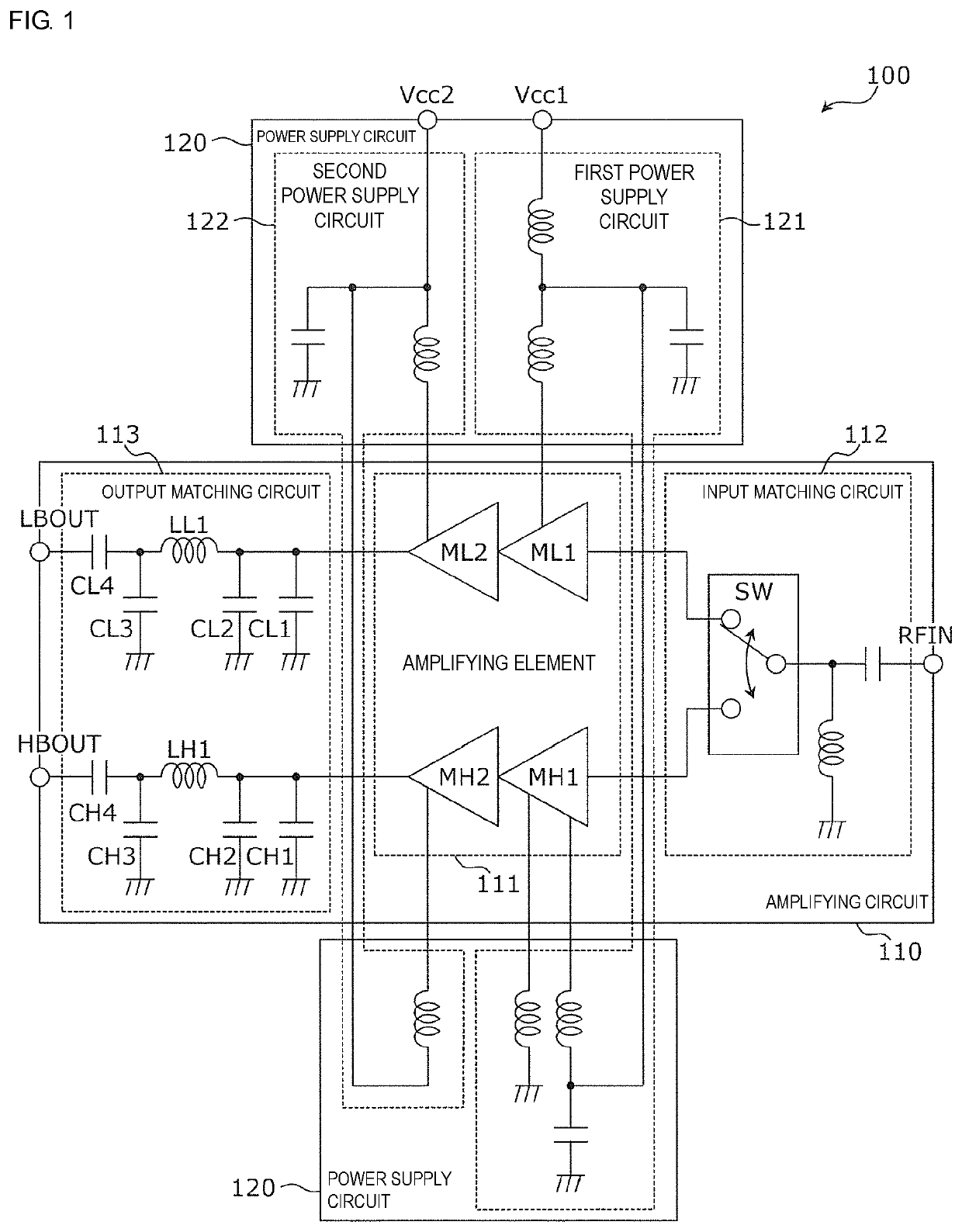
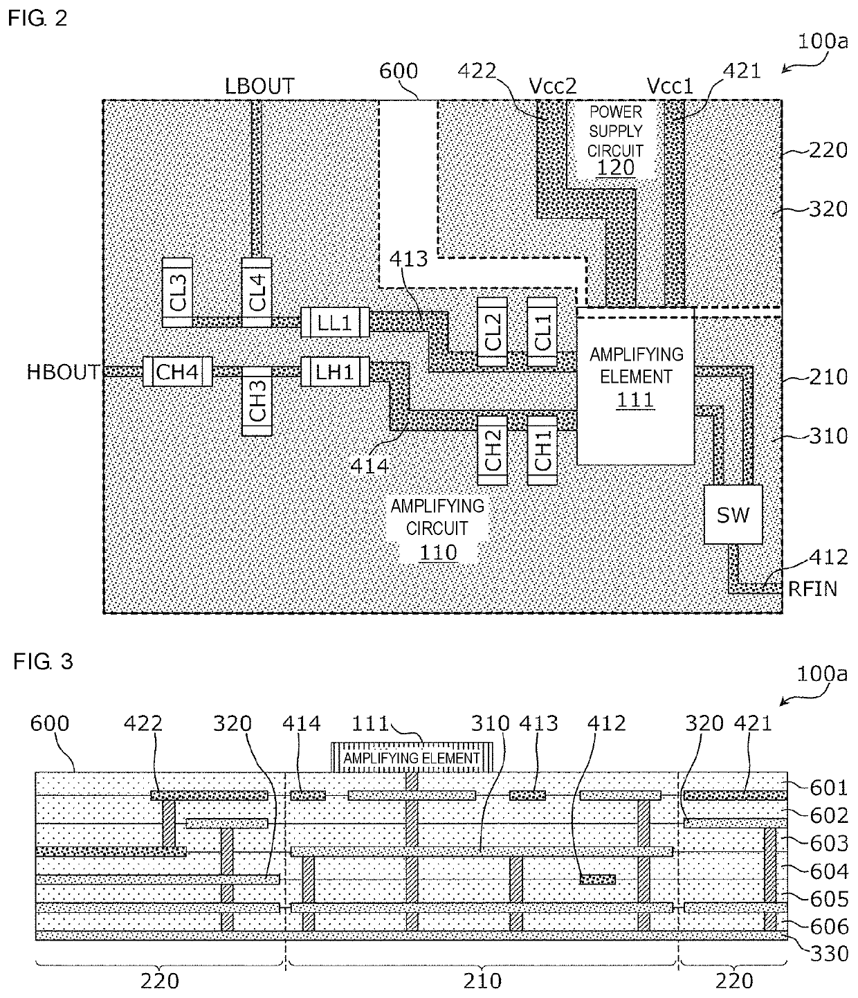
[0036]A radio frequency module according to a first embodiment is a multiband amplifier module provided in a multilayer substrate. The functional configuration of the radio frequency module will be described first, and the structural features of the radio frequency module will be described subsequently.

[0037]FIG. 1 is a circuit diagram illustrating an example functional configuration of the radio frequency module according to the first embodiment. As illustrated in FIG. 1, a radio frequency module 100 includes an amplifying circuit 110 that amplifies a radio frequency signal and a power supply circuit 120 that supplies power to the amplifying circuit 110.

[0038]The amplifying circuit 110 is a multiband amplifying circuit, receives a multiband input radio frequency signal RFIN including radio frequency signals in two frequency bands, and outputs output radio frequency signals LBOUT and HBOUT in the respective frequency bands obtained by amplifying the input radio frequency signal RFIN...

second embodiment

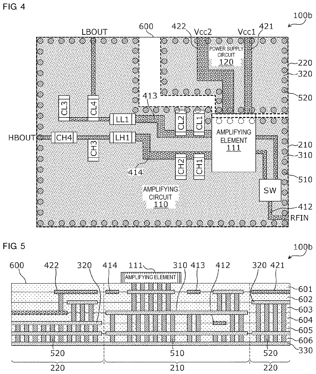
[0058]A radio frequency module according to a second embodiment differs from the radio frequency module according to the first embodiment in that the radio frequency module according to the second embodiment includes via conductors that are provided in a peripheral portion of each of the ground conductors and that are electrically connected to the ground conductor. A description of a matter similar to that in the first embodiment will be omitted below, and a different matter in the second embodiment will be mainly described.

[0059]FIG. 4 and FIG. 5 are schematic diagrams respectively illustrating an example planar structure and an example layered structure of a radio frequency module 100b according to the second embodiment. Unlike in the radio frequency module 100a illustrated in FIG. 2 and FIG. 3, in the radio frequency module 100b, a plurality of via conductors 510 and a plurality of via conductors 520 are respectively added to a peripheral portion of the ground conductor 310 and a...

third embodiment

[0061]A radio frequency module according to a third embodiment differs from the radio frequency module according to the first embodiment in that the ground conductors are separated into smaller portions and provided. A description of a matter similar to that in the first embodiment will be omitted below, and a different matter in the third embodiment will be mainly described.

[0062]FIG. 6 and FIG. 7 are schematic diagrams respectively illustrating an example planar structure and an example layered structure of a radio frequency module 100c according to the third embodiment. In the radio frequency module 100c, each of the regions 210 and 220 is further divided into a plurality of small portions.

[0063]The region 210 is divided into portions 211, 212, and 213 that do not overlap in plan view of the multilayer substrate 600. The amplifying element 111, the input matching circuit 112, and the output matching circuit 113 may be provided, for example, in each of the portions 211, 212, and 2...


PUM


Abstract

A radio frequency module includes: a multilayer substrate that includes a plurality of insulator layers; an amplifying circuit that is provided on the multilayer substrate and amplifies a radio frequency signal; a power supply circuit that is provided on the multilayer substrate and supplies power to the amplifying circuit; a ground conductor that is a first conductor pattern having a ground potential and used in the amplifying circuit; and a ground conductor that is a second conductor pattern having a ground potential and used in the power supply circuit. The ground conductors are physically separated from each other and provided in internal layers of the multilayer substrate.

Description

[0001]This is a continuation of International Application No. PCT / JP2018 / 010638 filed on Mar. 16, 2018 which claims priority from Japanese Patent Application No. 2017-074463 filed on Apr. 4, 2017. The contents of these applications are incorporated herein by reference in their entireties.BACKGROUNDTechnical Field[0002]The present disclosure relates to a radio frequency module and a communication device and specifically relates to a radio frequency module including an amplifying circuit provided on a multilayer substrate and ground conductors in the multilayer substrate.[0003]Currently, a radio frequency module including an amplifying circuit provided on a multilayer substrate and ground conductors in the multilayer substrate is available. For example, Patent Document 1 discloses a power amplifier module that is an example of such a radio frequency module.[0004]FIG. 11 is a circuit diagram illustrating the configuration of a power amplifier module 900 described in Patent Document 1. ...

Claims


Application Information

Patent Timeline
Patent Type & Authority Patents(United States)
IPC IPC(8): H01L23/498H01L23/66H05K1/02
CPCH01L23/49833H01L23/49822H01L23/49838H01L23/66H05K1/0298H01L2224/32225H05K2201/062H01L23/50H01L2223/6655H03F3/189
Inventor HONDA, AKIFUMI
Owner MURATA MFG CO LTD
Why Eureka
Try Eureka