Battery module having bus bar assembly

a battery module and bus bar technology, applied in the direction of secondary cells, battery components, battery servicing/maintenance, etc., can solve the problems of increasing the thickness of the member, and attaching a separate connecting member, etc., to achieve high electric resistance of the module bus bar, increase the use stability, and reduce the effect of heat generation

Active Publication Date: 2021-10-05
LG ENERGY SOLUTION LTD
View PDF35 Cites 0 Cited by
  • Summary
  • Abstract
  • Description
  • Claims
  • Application Information

AI Technical Summary

Benefits of technology

[0027]According to an aspect of the present disclosure, in a battery module, since a connection extending portion provided in the module bus bar can extend an area of a current path of the module bus bar, deformation of a shape of a bus bar and damage to internal components of the battery module caused by high heat generated during operation of the battery module due to high electric resistance of the module bus bar may be prevented, and thus use stability may be increased.
[0028]In addition, according to such an aspect of the present disclosure, since a lead contacting structure of a lower plate portion has a bent protruding shape in an outward direction, the lead contacting structure may have a wide contact area with left and right surfaces of an electrode lead protruding in a front-and-back direction. Accordingly, it is possible to prevent high resistance from being generated at a contact connecting portion between the electrode lead and the module bus bar, thereby increasing the life of the battery module and increasing stability.
[0029]Also, according to an aspect of the present disclosure, since laser welding may be performed while an end portion of an electrode lead is adhered to a surface of a module bus bar by a pressurizing bus bar provided at a bus bar assembly, a bonding process of high reliability may be performed.
[0030]Moreover, according to an aspect of the present disclosure, since a module bus bar and a pressurizing bus bar are stably fixed to the outside of a bus bar frame by a hook structure formed at the bus bar frame, efficiency of a welding process between an electrode lead and the module bus bar may be increased and durability of a finished product may be increased.
[0031]Also, according to an aspect of the present disclosure, since a detachment preventing structure formed at a bus bar frame of the present disclosure is configured to prevent a module bus bar from being detached to the outside, not only the module bus bar is stably fixed to the bus bar frame, but also frequent movement of the module bus bar is prevented, thereby effectively preventing a connecting structure between an electrode lead and the module bus bar from being damaged.
[0032]Moreover, according to another aspect of the present disclosure, in a module bus bar of the present disclosure, since a connection extending portion is inserted into a fitting groove formed at a partition wall of a bus bar frame to be firmly fixed and the fitting groove guides the module bus bar to be fixed at an accurate location, manufacturing time can be reduced.

Problems solved by technology

However, when a cross-sectional area of a current path of a terminal bus bar where a module terminal of the battery module is formed is narrow, the bus bar may be deformed or components connected to the bus bar may be damaged due to heating of the bus bar when a high current is applied in a high power environment of the battery module.
Also, increasing a thickness of a member or attaching a separate connecting member so as to increase the cross-sectional area of the current path of the bus bar is not appropriate because manufacturing costs are increased.

Method used


Image

  • Battery module having bus bar assembly
  • Battery module having bus bar assembly
  • Battery module having bus bar assembly

Examples


Embodiment Construction

[0045]Hereinafter, preferred embodiments of the present disclosure will be described in detail with reference to the accompanying drawings. Prior to the description, it should be understood that the terms used in the specification and the appended claims should not be construed as limited to general and dictionary meanings, but interpreted based on the meanings and concepts corresponding to technical aspects of the present disclosure on the basis of the principle that the inventor is allowed to define terms appropriately for the best explanation.

[0046]Therefore, the description proposed herein is just a preferable example for the purpose of illustrations only, not intended to limit the scope of the disclosure, so it should be understood that other equivalents and modifications could be made thereto without departing from the scope of the disclosure.

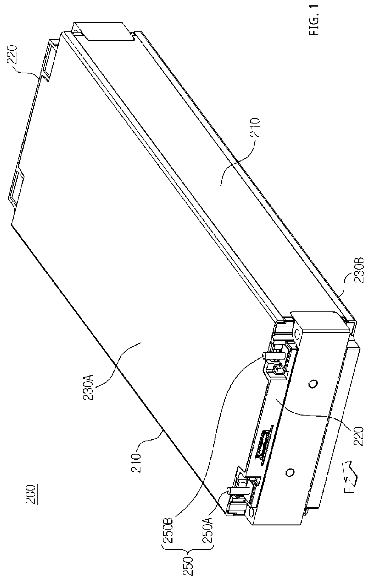
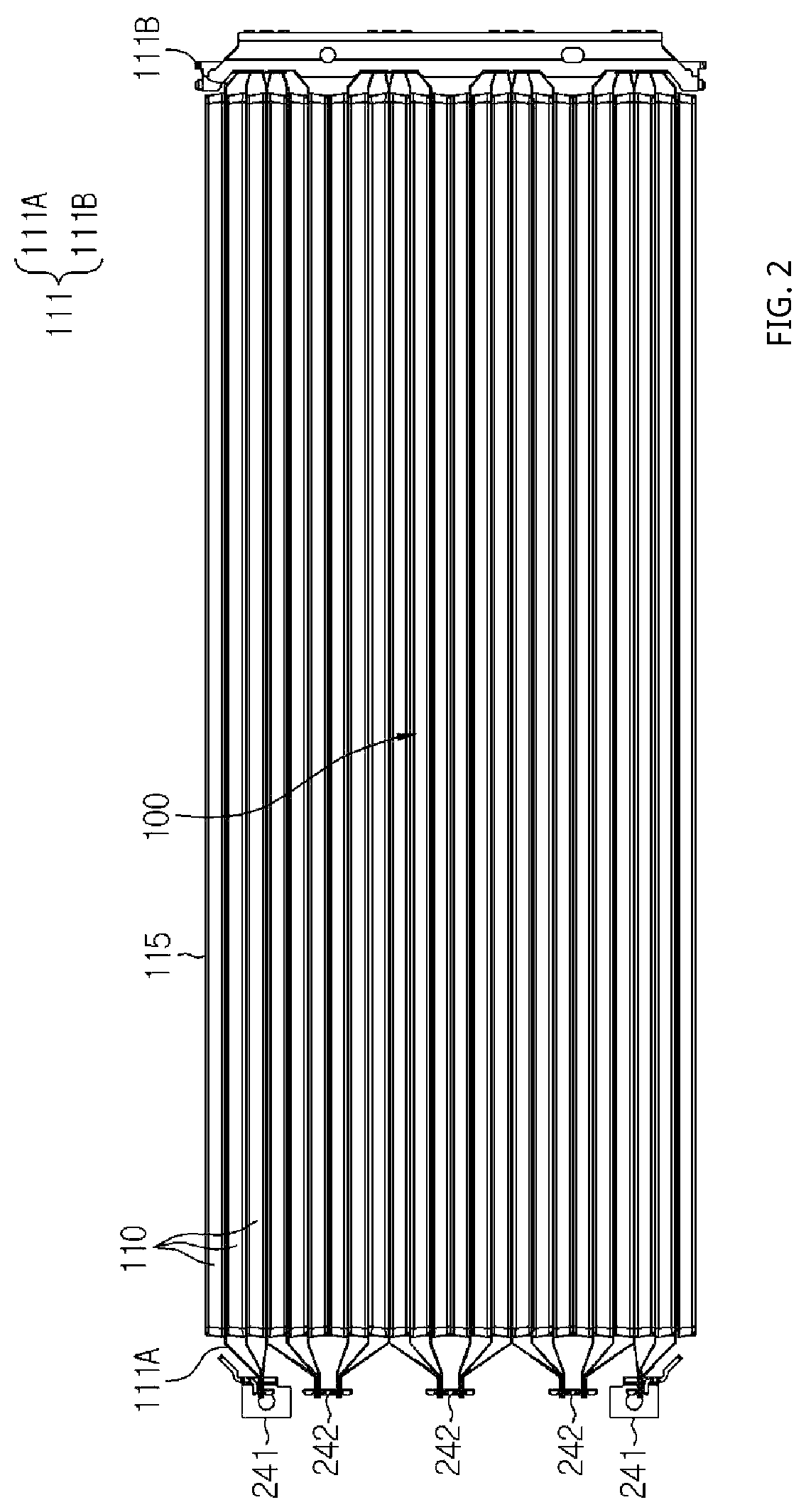
[0047]FIG. 1 is a perspective view schematically showing a battery module according to an embodiment of the present disclosure. FIG. 2 i...


PUM

PropertyMeasurementUnit
energy densityaaaaaaaaaa
shapeaaaaaaaaaa
polarityaaaaaaaaaa

Abstract

Provided is a battery module in which heat generation of a current path of a module bus bar mounted on a bus bar assembly is reduced. The battery module includes: a cell assembly including a secondary batteries that each include electrode leads; and a bus bar assembly including: a module bus bar including an upper plate portion and a lower plate portion that electrically connect the secondary batteries and the module terminal and each have at least one region separated from each other, a connection extending portion that extends to one side end portion of each of the upper plate portion and the lower plate portion, and a bent connecting portion that is combined to the module terminal provided at a top of the upper plate portion; and a pressurizing bus bar pressurizing the electrode leads such that end portions of the electrode leads contact the lower plate portion.

Description

CROSS-REFERENCE TO RELATED APPLICATIONS[0001]The present application is a national phase entry under 35 U.S.C. § 371 of International Application No. PCT / KR2018 / 015879, filed Dec. 13, 2018, published in Korean, which claims priority to Korean Patent Application No. 10-2017-0175191 filed on Dec. 19, 2017 in the Republic of Korea, the disclosures of which are incorporated herein by reference.TECHNICAL FIELD[0002]The present disclosure relates to a battery module including a bus bar assembly, and more particularly, to a battery module in which heat generation on a current path of a module bus bar mounted on a bus bar assembly is reduced.BACKGROUND ART[0003]Currently commercialized secondary batteries include nickel cadmium batteries, nickel hydrogen batteries, nickel zinc batteries, lithium secondary batteries, etc. and the lithium secondary batteries thereamong are receiving attention according advantages of free charging / discharging, a very low self-discharge rate, and high energy de...

Claims


Application Information

Patent Timeline
Patent Type & Authority Patents(United States)
IPC IPC(8): H01M50/531H01M10/42H01M50/20H01M50/543H01M50/211H01M50/296H01M50/507H01M50/514H01M50/522H01M50/548
CPCH01M50/531H01M10/425H01M50/20H01M50/543H01M2010/4271H01M2220/20Y02E60/10H01M50/507H01M50/522H01M50/514H01M50/548H01M50/296H01M50/211H01M50/502
Inventor KIM, KYUNG-MOMUN, JEONG-OPARK, JIN-YONGLEE, JUNG-HOONCHI, HO-JUNE
Owner LG ENERGY SOLUTION LTD
Why Eureka
Try Eureka