
Ophthalmic injection device

a technology of ophthalmic injection and ophthalmic nerve, which is applied in the direction of eye treatment, process and machine control, etc., can solve the problems of undetected permanent detachment of the retina, inability to achieve significant therapeutic concentrations in the posterior portion of the eye and the retina with topical administration methods, etc., to achieve high-controlled delivery of therapeutic agents, prevent leakage of injected material, and minimize trauma to sensitive ocular tissues

Active Publication Date: 2021-10-26
OXULAR LTD
View PDF53 Cites 0 Cited by
  • Summary
  • Abstract
  • Description
  • Claims
  • Application Information

AI Technical Summary

Benefits of technology

This patent describes an ophthalmic injector that can deliver a therapeutic agent through a small needle. The small needle prevents leakage and minimizes damage to sensitive ocular tissues. The device has a valve that allows control over the injection rate, and it can be used with one hand to inject into tissues spaces that are not normally open. The device also has a tissue interface that stabilizes the tissue surface and acts as a seal to prevent leakage during injection. Overall, this device provides highly controlled delivery of therapeutic agents with minimal trauma to the eye.

Problems solved by technology

Some drugs may be delivered to the front, anterior portion of the eye by drops but reaching significant therapeutic concentrations in the posterior portion of the eye and the retina is generally not achieved with topical methods of administration.
However for subretinal injections, the injection must be performed in a manner to prevent trauma to the sensitive retinal tissues or formation of a bleb that may result in undesired permanent detachment of the retina.

Method used


Image

  • Ophthalmic injection device
  • Ophthalmic injection device
  • Ophthalmic injection device

Examples


example 1

on of One Embodiment of an Injection Device

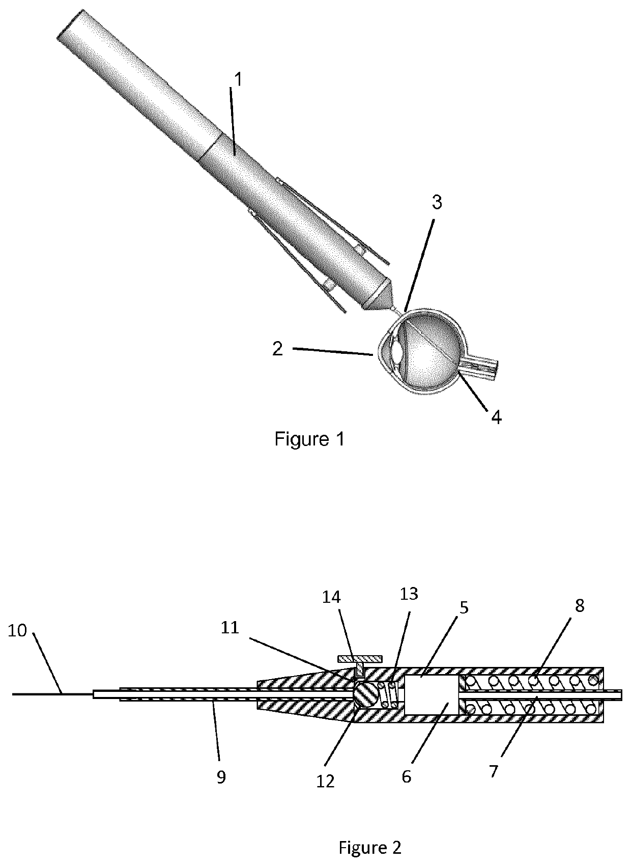
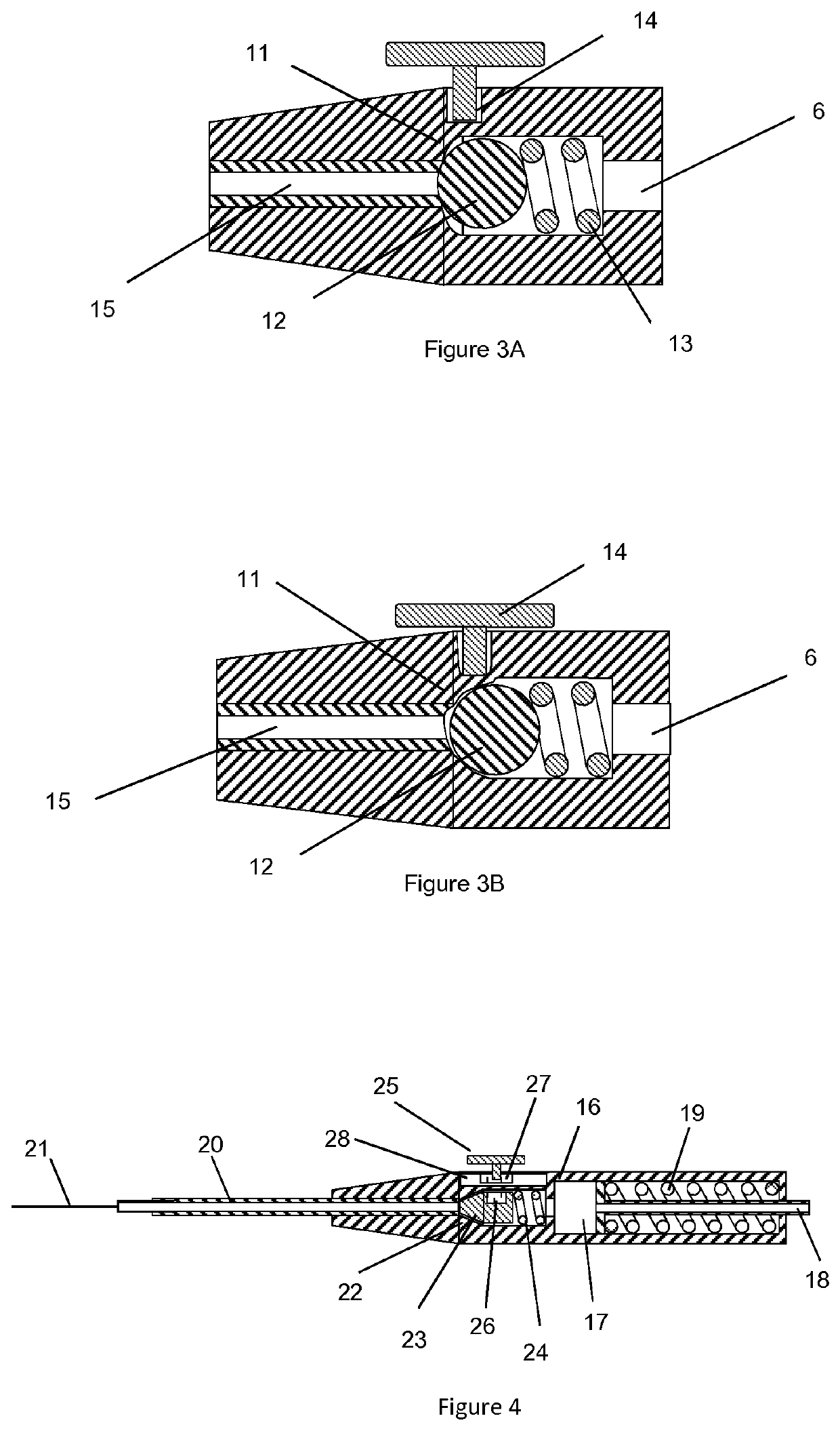
[0073]The device according to one embodiment similar to the device shown in FIG. 2 was fabricated. A valve body 14.75 mm long was molded from silicone rubber of durometer 50 Shore A (Nusil, Part No. MED-4950) which comprises a proximal valve chamber of 3.43 mm diameter and 6.5 mm depth, dimensioned to accept a 3.175 mm diameter stainless steel spherical ball acting as a valve sealing element and a valve compression spring of 3.175 mm diameter and 8.26 mm long fabricated from 0.3 mm diameter wire. The valve body incorporated a valve seat of 1.91 mm diameter and 2.35 mm depth distal to the chamber, configured such that the ball acting as the valve sealing element was compressed against the valve seat by the valve spring. The molded valve body incorporated a compression flange 9.25 mm diameter and 1.25 mm thick on the proximal end. The distal end of the valve body was configured with a lumen to accept a 23 gauge tube that was press fit into th...

example 2

f Injection Device

[0079]A device according to Example 1 was fabricated. De-ionized water as the injection material was drawn up into a 1 ml syringe and the syringe was attached to the Luer fitting of the plunger check valve. Approximately 0.3 ml of water was filled into the reservoir causing the plunger to retract proximally and compressing the plunger spring thereby providing a force on the injection material in the device reservoir. No injection material flowed out of the distal cannula. The actuation button was depressed and water was seen flowing out of the distal cannula. The actuation button was released and the fluid flow stopped. The action was repeated with the same results.

example 3

f Injection Device in an Eye

[0080]A device according to Example 1 was fabricated. A porcine cadaver eye was prepared for using the device for a subretinal injection. The procedure was performed under a stereo microscope for ease of visualization. In order to access the retina in the cadaver eye, the cornea was completely removed at the limbus. The natural lens was carefully excised by cutting the zonular fibers away from the lens then lifting the lens out of the globe. The vitreous was removed en-masse leaving the retina behind. The device was loaded with 0.2 ml of 0.1% fluorescein solution using a 1 ml syringe filled with the fluorescein solution attached to the plunger check valve. The distal cannula was carefully inserted through the retina tissues and was advanced. The cannula deflected across the choroidal surface, traversing a short distance parallel to the tissues.

[0081]The actuation button was depressed for approximately 1.5 seconds during which time fluorescein solution cou...


PUM


Abstract

A device for controlled delivery of an injection material to tissue spaces of an eye that are not normally open, such as the subconjunctival space, the suprachoroidal space and the subretinal space. The device comprises an elongated body with a hollow cannula at the distal end, a slidable plunger at the proximal end, and a reservoir for the material to be injected residing between the cannula and the plunger. The plunger is mechanically coupled to a source of force such as a spring or pressurized gas reservoir such that an injection force is applied to the injection material within the device prior to delivery of the injection material into an eye. A valve that is normally closed to prevent flow of the injection material during application of the injection force is placed in the flow path between the cannula and reservoir. Due to the injection force placed on the injection material, actuation of the valve allows controlled flow from the reservoir through the cannula and into the tissue space.

Description

RELATED APPLICATIONS[0001]This application is a 35 U.S.C. § 371 national phase application of PCT Application No. PCT / EP2016 / 072024, filed Sep. 16, 2016, which claims priority to U.S. Provisional Application 62 / 220,165, filed Sep. 17, 2015. Any and all applications for which a foreign or domestic priority claim is identified in the Application Data Sheet as filed with the present application are hereby incorporated by reference under 37 CFR 1.57. Where allowable all patents and patent applications referred to herein are hereby incorporated by reference in their entirety.BACKGROUND OF INVENTION[0002]Due to the unique anatomy and physiology of the eye, multiple barriers exist that prevent significant transport of drugs to ocular tissues. The blood vessels of the eye have restricted permeability due to the blood-ocular barriers that regulate intraocular fluid. Due to these blood-ocular barriers, systemically administered drugs do not reach significant concentration in ocular tissues. S...

Claims


Application Information

Patent Timeline
Patent Type & Authority Patents(United States)
IPC IPC(8): A61M5/168A61F9/00A61M5/20A61M5/145A61M5/315A61M5/32A61M5/31
CPCA61F9/0017A61M5/1452A61M5/16881A61M5/2053A61M5/315A61M5/329A61M2005/3128A61M2205/8218A61M2210/0612A61P27/02A61P27/06A61P29/00A61P31/00A61F9/0008A61F9/007A61F9/00736A61M5/178
Inventor YAMAMOTO, RONALD K.CONSTON, STANLEY R.BLEY, ROBERT STEVEN
Owner OXULAR LTD
Learn More