Delivery system for deploying a self-expanding tube, and method of deploying a self-expanding tube

a self-expanding tube and delivery system technology, applied in the field of self-expanding tubes, can solve the problems of reducing affecting the optimal deployment of the self-expanding tube in this context, and affecting the service life of the tube, so as to achieve sufficient coverage, reduce the porosity, and reduce the effect of pressure on the surrounding tissu

Active Publication Date: 2021-11-02
OXFORD ENDOVASCULAR LTD
View PDF18 Cites 0 Cited by
  • Summary
  • Abstract
  • Description
  • Claims
  • Application Information

AI Technical Summary

Benefits of technology

[0005]Using a self-expanding tube, sometimes referred to as a stent, alone to treat the aneurysm is a promising way to avoid the problems stated above. In this method, a tube with an area of relatively low porosity is placed across the aneurysm neck in such a way as to redirect blood flow away from the sac and trigger formation of a thrombus within the aneurysm. Because the aneurysm solidifies naturally on itself, there is less danger of its rupture. Furthermore, because no coil is involved in this method, the aneurysm will gradually shrink as the thrombus is absorbed. Consequently, the pressure applied on the surrounding tissue can be removed. It is difficult, however, to deploy a self-expanding tube optimally in this context. The tube has to be flexible enough to pass through and adapt to the shape of the very tortuous blood vessels in the brain while at the same time providing sufficient coverage (low porosity) to redirect blood flow away from the aneurysm to an adequate extent. The tube needs to be deployed reliably and controllably, with a minimal risk of damage to the tube or surrounding tissue.
[0008]By distributing a strong longitudinal engagement between the tube and the elongate body over a large proportion of the length of the tube it is possible to reliably deploy tubes with a minimal risk of damage to their structural integrity even in the case where the tubes have low longitudinal stiffness. Alternative techniques based on engaging with the tube only in localised regions (e.g. by pushing from one end or pulling from the other end) are likely to damage tubes having low longitudinal stiffness. Delivery systems according to embodiments of the present disclosure thus widen the range of self-expanding tubes that can be delivered reliably, opening up in particular the possibility of reliably deploying stents of low longitudinal stiffness.
[0009]In an embodiment, the elongate body is configured to self expand from a radially contracted state to a radially expanded state in a process involving longitudinal shortening of the elongate body relative to the longitudinal axis of the tubular member. This causes the elongate body to contract as the tube is being deployed, thereby reducing or avoiding extension of the elongate body longitudinally beyond the tube during deployment and reducing or avoiding risk of injury by the elongate body.

Problems solved by technology

Furthermore, because no coil is involved in this method, the aneurysm will gradually shrink as the thrombus is absorbed.
It is difficult, however, to deploy a self-expanding tube optimally in this context.
Alternative techniques based on engaging with the tube only in localised regions (e.g. by pushing from one end or pulling from the other end) are likely to damage tubes having low longitudinal stiffness.

Method used


Image

  • Delivery system for deploying a self-expanding tube, and method of deploying a self-expanding tube
  • Delivery system for deploying a self-expanding tube, and method of deploying a self-expanding tube
  • Delivery system for deploying a self-expanding tube, and method of deploying a self-expanding tube

Examples


Embodiment Construction

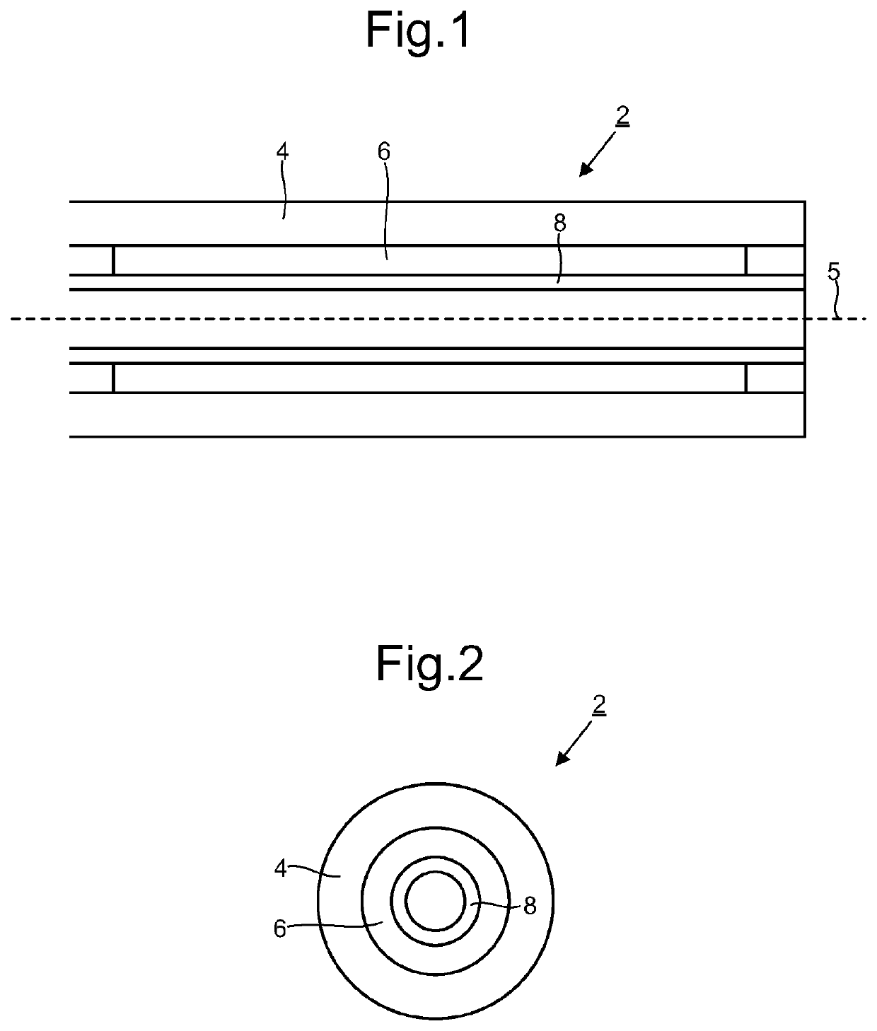
[0020]Embodiments of the present disclosure provide a delivery system 2 for deploying a self-expanding tube 6 into a blood vessel. The tube 6 may be referred to as a stent. In a preferred embodiment the tube 6 is configured to be positioned across the opening of an aneurismal sac to redirect blood flow away from the aneurismal sac. The redirection of blood flow is preferably sufficient to promote thrombus formation within the sac.

[0021]The delivery system 2 comprises a tubular member 4 configured for insertion into the blood vessel. A distal end of the tubular member 4 is depicted in FIGS. 1 and 2. Tubular members 4 configured for such use are well known in the art of minimally invasive surgery. The tubular member 4 will typically be cylindrical and dimensioned such that its distal end can be brought to the region to be treated with the body. In the case of treating a cerebral aneurysm, the tubular member 4 will be configured so that it can be navigated to the opening of the aneuris...


PUM


Abstract

Delivery systems for deploying a self-expanding tube into a blood vessel are disclosed. In one arrangement, a tubular member is provided that is configured for insertion into the blood vessel. An elongate body extends within a lumen of the tubular member. A self-expanding tube is positioned radially between the tubular member and the elongate body. Over at least 50% of the length of the self-expanding tube, at least a portion of the self-expanding tube engages outwardly with the tubular member and inwardly with the elongate body. A longitudinal engagement force acting between the self-expanding tube and the tubular member and a longitudinal engagement force acting between the self-expanding tube and the elongate body are such that, during all stages of deployment of the self-expanding tube in use by longitudinal retraction of the tubular member relative to the elongate body, there is substantially no relative movement longitudinally between the elongate body and any portion of the self-expanding tube that remains in engagement with the elongate body.

Description

CROSS-REFERENCE TO RELATED APPLICATIONS[0001]This application is a continuation of International Patent Application Number PCT / GB2018 / 050770 filed Mar. 23, 2018, which claims priority to GB Patent Application Number 1704721.8 filed Mar. 24, 2017, the contents of which are incorporated herein by reference in their entirety.BACKGROUND OF THE INVENTION[0002]The present invention relates to deploying a self-expanding tube, particularly for use in redirecting blood flow away from an aneurismal sac.[0003]An intracranial aneurysm is a weak region in the wall of an artery in the brain, where dilation or ballooning of the arterial wall may occur. Histologically, decreases in the tunica media, the middle muscular layer of the artery, and the internal elastic lamina cause structural defects. These defects, combined with hemodynamic factors, lead to aneurismal out-pouchings. Intracranial aneurysms are quite common diseases with a prevalence ranging from one to five percent among adult populatio...

Claims


Application Information

Patent Timeline
Patent Type & Authority Patents(United States)
IPC IPC(8): A61F2/966
CPCA61F2/966A61F2210/0014
Inventor KEEBLE, DUNCANHSIEH, GEORGE
Owner OXFORD ENDOVASCULAR LTD
Why Eureka
Try Eureka