
Wind turbine safety system

a safety system and wind turbine technology, applied in the direction of wind turbines, mechanical equipment, machines/engines, etc., can solve the problems of ice accumulation, ice throw, ice throw, etc., and achieve the effect of reducing the risk zone of ice throw

Active Publication Date: 2021-11-09
VESTAS WIND SYST AS
View PDF16 Cites 0 Cited by
  • Summary
  • Abstract
  • Description
  • Claims
  • Application Information

AI Technical Summary

Benefits of technology

The present invention is about a wind turbine system that can identify when there is a possibility of ice coming onto the turbine blades and change the way it operates to prevent this from happening. This means that the wind turbine can keep generating power even when there is ice on the blades. The system can change things like the pitch of the blades and how they vibrate to get the ice to move off the blades. This results in less damage to the wind turbine and allows it to keep producing energy.

Problems solved by technology

Wind turbines situated in cold climates can suffer from icing events where ice may be formed on the surface of the wind turbine blades due to freezing water on the cold surface.
The accumulation of ice on the surface of a blade can result in undesirable consequences.
For example, ice accretion on the wind turbine blades presents a risk of ice throw damaging nearby properties or injuring people or animals in the vicinity of the wind turbine as ice attached to a blade may become loose and be thrown away from the wind turbine by the rotation of the blade.
Legislation and operational requirements in several countries force wind farms to be shutdown if there is a risk of ice accretion on the wind turbine blades as there is a subsequent risk that the ice may break loose and be thrown from the wind turbine.
Therefore, it is disadvantageous to simply shutdown one or more wind turbines (or a complete wind farm) on the basis of ice accretion, or expected ice accretion, on the wind turbine blades as this reduces the AEP of the wind turbines / wind farm.

Method used


Image

  • Wind turbine safety system
  • Wind turbine safety system
  • Wind turbine safety system

Examples


Embodiment Construction

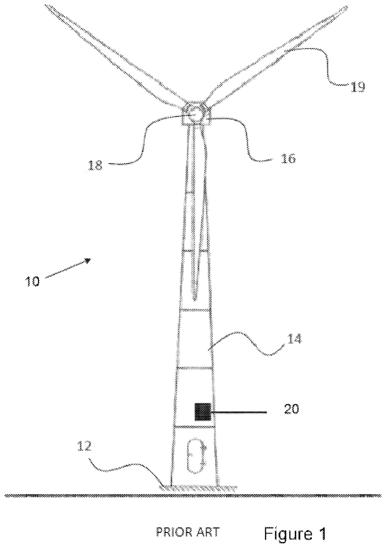
[0033]FIG. 1 shows a schematic of a typical wind turbine 10. The wind turbine 10 is mounted on a base 12 which may be onshore foundations or off-shore platforms or foundations. The wind turbine includes a tower 14 having a number of tower sections. A nacelle 16 is located and attached to the top of tower 14. A wind turbine rotor, connected to the nacelle 16, includes a hub 18 and at least one wind turbine blade 19, where in FIG. 1 three wind turbine blades are shown although any number of wind turbine blades 19 may be present depending on the design and implementation of the wind turbine 10. The wind turbine blades 19 are connected to the hub 18 which in turn is connected to the nacelle 16 through a low speed shaft which extends out of the front of the nacelle 16. The wind turbine 10 typically includes a wind turbine controller 20 which may be located within the wind turbine, e.g. in the hub 18, in the nacelle 16, in the tower 14, or any other suitable location within or near the wi...


PUM


Abstract

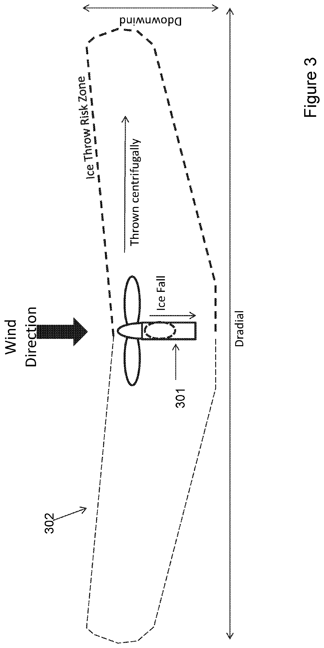
The present invention relates to a method, controller, wind turbine and wind farm that advantageously determines an ice throw risk zone (302) for a wind turbine (301), wherein the ice throw risk zone (302) defines an area surrounding the wind turbine (301) within which ice can be thrown from one or more blades of the wind turbine (301); determining whether the determined ice throw risk zone (302) impinges one or more exclusion zones; and if the determined ice throw risk zone (302) impinges one or more exclusion zones, determining an alteration to one or more operating parameters of the wind turbine (301) in order to alter the ice throw risk zone (302) such that the determined ice throw risk zone (302) does not impinge the one or more exclusion zones.

Description

[0001]The present invention relates to a wind turbine safety system and, in particular, to an ice throw risk safety system.BACKGROUND[0002]Wind turbines generate electrical power from wind energy and can be situated on land or off-shore. Wind turbines situated in cold climates can suffer from icing events where ice may be formed on the surface of the wind turbine blades due to freezing water on the cold surface. The accumulation of ice on the surface of a blade can result in undesirable consequences.[0003]For example, ice accretion on the wind turbine blades presents a risk of ice throw damaging nearby properties or injuring people or animals in the vicinity of the wind turbine as ice attached to a blade may become loose and be thrown away from the wind turbine by the rotation of the blade.[0004]Legislation and operational requirements in several countries force wind farms to be shutdown if there is a risk of ice accretion on the wind turbine blades as there is a subsequent risk tha...

Claims


Application Information

Patent Timeline
Patent Type & Authority Patents(United States)
IPC IPC(8): F03D80/40F03D17/00F03D7/04
CPCF03D80/40F03D7/048F03D17/00F05B2260/821F05B2270/107Y02E10/72
Inventor BADGER, PAULNIELSEN, BRIAN DAUGBJERGTHOMSEN, PETER TRANUM
Owner VESTAS WIND SYST AS
Learn More