Ball picking robot

a robot and ball technology, applied in the field of sports equipment, can solve the problems of affecting training efficiency, wasting time, and athletes may step on the robot and get injured, so as to improve the flexibility of the robot, improve the efficiency of ball picking, and reduce labor intensity

Active Publication Date: 2021-11-23
CHONGQING VOCATIONAL INST OF ENG +2
View PDF8 Cites 0 Cited by
  • Summary
  • Abstract
  • Description
  • Claims
  • Application Information

AI Technical Summary

Benefits of technology

[0026](1) The robot can move automatically along a set route by a walking mechanism. It can also move in all directions and has a function of turning through the steering and speed adjustment of two sets of step motors, which improves the flexibility of the robot and enables it to move to all corners to pick up balls. Hence, the ball picking efficiency is improved and the labor intensity is reduced.
[0027](2) By using a ball picking basket comprising a plurality of elastic cords (e.g. rubber bands) and a ball picking basket frame, it is possible that a ball can enter the ball picking basket from the gap surrounded by adjacent elastic cords when the ball picking basket is pressed on top of the ball. However, there will be a decline in elasticity of elastic cords (e.g. rubber bands) after long-term use. When such elastic cords are pressed against a ball, the ball will be deformed correspondingly and cannot be successfully locked into the ball picking basket composed of elastic cords, resulting in a decline in the ball picking efficiency; at the same time, the structure of the ball picking robot is too complex to replace the ball picking basket conveniently. Therefore, the present invention adopts an air cylinder for driving the ball picking basket to move downwards so that a downward instantaneous acting force can be applied to the ball picking basket for quickly and accurately picking up a ball, thereby reducing the wear and tear on elastic cords, slowing down the elastic falling speed of elastic cords and prolonging the service life of the ball picking basket. In addition, an either-rotation motor is used to drive the rotary impeller and the micro air pump at the same time, which reduces the number of motors in the whole robot and the weight of the whole robot, and improves the running reliability and stability. A three-way solenoid valve is used to control the air inlet of the air cylinder. In this case, only one air storage tank is to be provided for the air inlet of different air chambers of the air cylinder, thus achieving the up-and-down movement of the air cylinder. The present invention uses a shielding assembly of a tape structure. On the one hand, the ruler blocks the opening of the ball picking basket to prevent a ball from falling off from the ball picking basket; on the other hand, after the ball picking is completed, the ruler can be retracted to expose the opening of the ball picking basket and enable the ball to enter the ball discharging channel through the opening.
[0028](3) The first ball pushing assembly is provided to push balls picked up in the ball picking basket into the ball discharging channel, so as to empty the ball picking basket in time and improve the ball picking efficiency. The pushing assembly is provided to push balls in the ball discharging channel to below the rotary ball discharging assembly. Because of the rotary ball discharging assembly, it is possible that a ball, when entering the gap between adjacent blades of the rotary impeller, can move backward into the ball storage mechanism through the rotating rotary impeller.
[0029](4) The base plate of the ball storage mechanism is arranged to have a slope from front to back, so that a ball entering the ball storage mechanism will be able to move backward along the base plate having a slope rather than return back to the rotary ball discharging assembly. The first gear drive assembly, the second gear drive assembly, the third gear drive assembly and the fourth gear drive assembly are provided to open the door body when the second push plate pushes a ball in the ball storage mechanism backward. The first gear drive assembly comprising a plurality of gears and having a drive ratio is able to adjust the opening speed of the door body, and make the door body open completely when the second push plate moves backward to the end of the ball storage mechanism. Therefore, the second ball pushing assembly and the door body can be protected to a certain extent so that various components will not be damaged due to interfere with each other.

Problems solved by technology

If not picking them up timely, athletes may step on them and get injured resulting from a fall.
However, manual picking wastes time, affects the training efficiency, and requires great labor intensity for ball pickers.
With the progress of science and technology, many ball picking robots have been developed in recent years, but existing ball picking robots generally have some disadvantages such as complex structure, cumbersome operation, low picking success rate, low picking efficiency and the like.
Because table tennis balls are light and rolls easily, they not necessarily enter a space between two blades of the first rotary impeller accurately.
Therefore, during the rotation of the first rotary impeller, only a very small number of table tennis balls, or even no table tennis balls enter the space between two blades of the first rotary impeller, which will cause a waste of energy due to the idling of the first rotary impeller, and lead to long table tennis ball picking time and low picking success rate.
To pick up all table tennis balls into the temporary ball storage bin, the first rotary impeller shall be rotated constantly or the position of the robot constantly shall be adjusted to change the position of the rotary impeller so that the table tennis balls fall within the rotation range of the first rotary impeller, which is a very tedious adjustment process and greatly reduces the picking success rate and picking efficiency.

Method used


Image

  • Ball picking robot
  • Ball picking robot
  • Ball picking robot

Examples


Embodiment Construction

[0039]The present invention will be further explained with reference to the drawings.

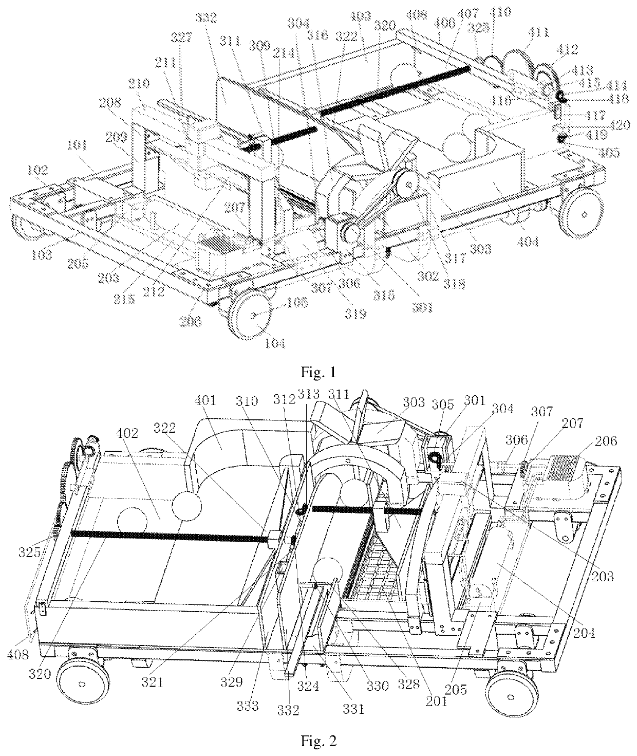
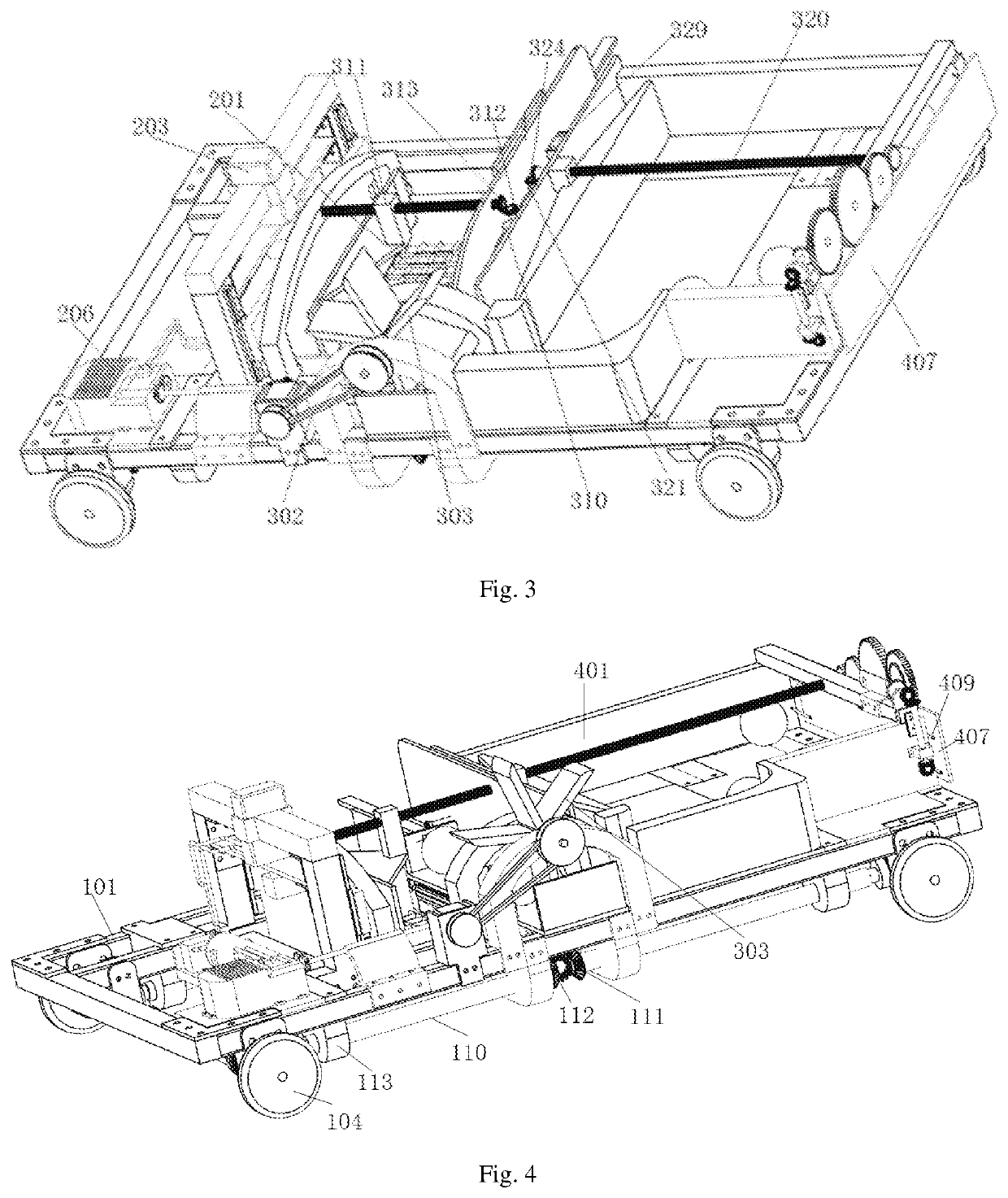
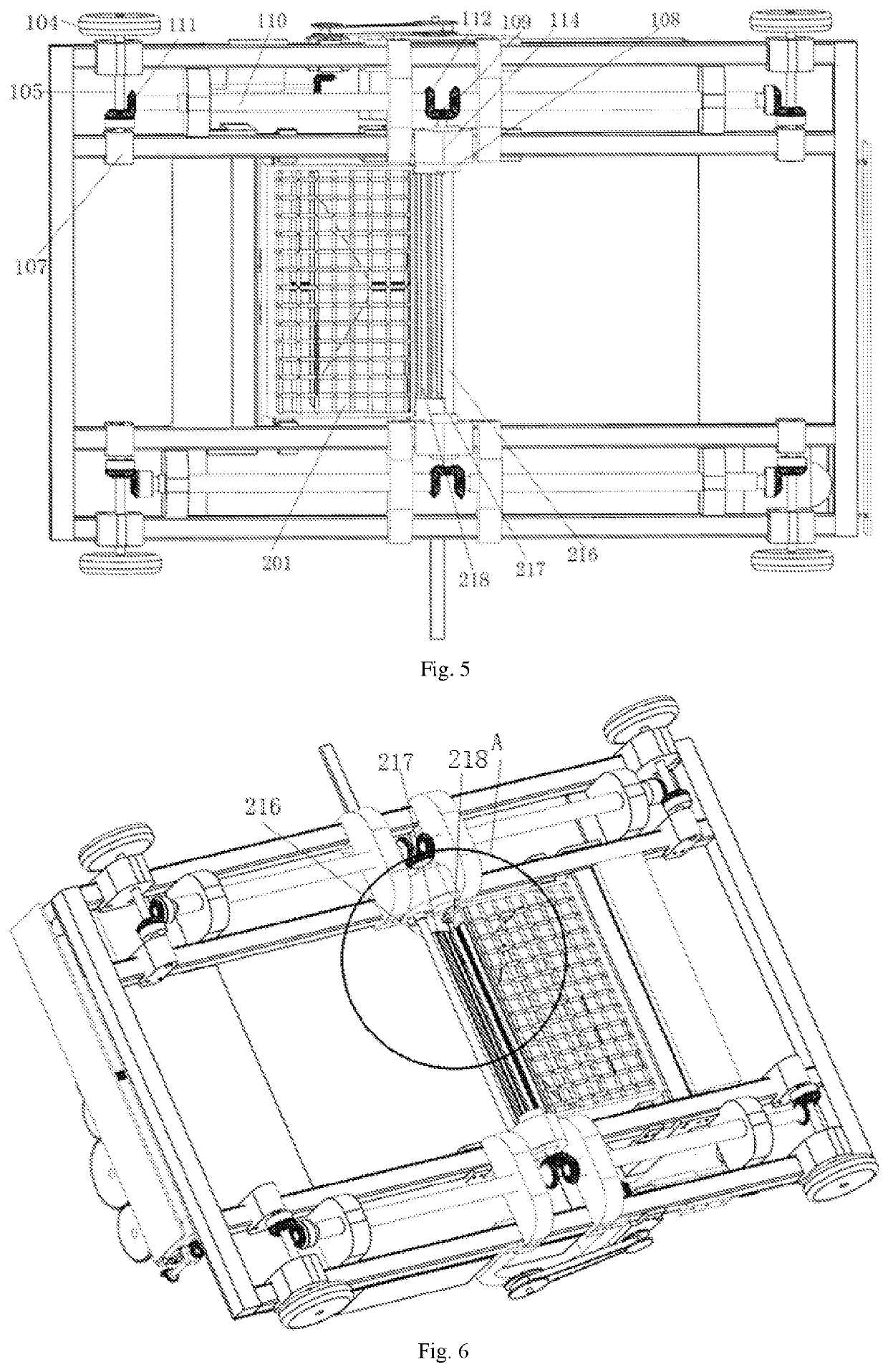
[0040]As shown in FIGS. 1-6, a ball picking robot comprises a walking mechanism, and a ball picking mechanism, a ball pushing mechanism and a ball storage mechanism mounted on the walking mechanism.

[0041]The walking mechanism comprises a frame 101, a plurality of wheel assemblies mounted on the frame 101, and a second drive assembly for driving the rotation of the wheel assemblies. The frame 101 comprises an outer frame 102 and an auxiliary member 103 arranged within the outer frame 102. The frame 101 is made of steel, which improves the structural strength and provides solid support for other mechanisms. The wheel assembly comprises a wheel 104, a wheel axle 105 and a fifth gear sleeved on the wheel axle 105. Two ends of the wheel axle 105 are fixed to the frame 101 by a wheel axle bracket 107, and the wheel axle 105 is in running fit with the wheel axle bracket 107 through a bearing. The second dr...


PUM


Abstract

The present invention relates to a ball picking robot, comprising a walking mechanism, a ball picking mechanism, a ball pushing mechanism and a ball storage mechanism. The ball picking mechanism comprises a ball picking basket, an air cylinder used for driving the ball picking basket to move up and down, an air storage tank used for providing an air source for the air cylinder, a solenoid valve arranged at the air outlet of the air storage tank, a micro air pump connected to the air storage tank, and a shielding assembly arranged at an opening in the rear end of the ball picking basket. A first gear is mounted at the input end of the micro air pump. The ball pushing mechanism comprises a rotary ball discharging assembly, comprising an either-rotation motor, a rotary impeller connected to a first output shaft of the either-rotation motor through a belt assembly.

Description

CROSS-REFERENCE TO RELATED APPLICATION[0001]This application claims priority from the Chinese patent application 202010672228.0 filed Jul. 14, 2020, the content of which are incorporated herein in the entirety by reference.TECHNICAL FIELD[0002]The present invention relates to the technical field of sports equipment, in particular to a ball picking robot.BACKGROUND[0003]With the improvement of living standards, ball games such as table tennis, badminton and golf are becoming more and more popular. In the play process, especially when practicing a ball game, it is very common that a lot of balls are hit all over the place. If not picking them up timely, athletes may step on them and get injured resulting from a fall. People usually bend over to pick up a large number of balls scattered on the court with their hands or by a hand-held ball picking tool. Balls have to be repeatedly picked up in the daily training process. However, manual picking wastes time, affects the training efficien...

Claims


Application Information

Patent Timeline
Patent Type & Authority Patents(United States)
IPC IPC(8): A63B47/02B65G67/02
CPCA63B47/021B65G67/02A63B2047/022A63B2209/14A63B2102/16
Inventor XU, HAOHE, JIASHUNLIU, JIANGXU, YIFEIPAN, FUSHENG
Owner CHONGQING VOCATIONAL INST OF ENG
Why Eureka
Try Eureka