Intramedullary threaded nail for radial cortical fixation

a technology of radial cortical fixation and threaded nails, which is applied in the field of intramedullary threaded nails for radial cortical fixation, can solve the problems of loss of muscle, proprioception and nerve health, and injury to the mid-hand and mid-foot, and achieve the effect of avoiding harm to the narrower leading end of the lower material

Active Publication Date: 2021-12-07
EXSOMED CORP
View PDF214 Cites 0 Cited by
  • Summary
  • Abstract
  • Description
  • Claims
  • Application Information

AI Technical Summary

Benefits of technology

[0016]The present invention solves the problems associated with repairing a metacarpal or metatarsal fracture or dislocation by providing a device that is a unique combination of a nail and a screw, which can be inserted into the bone without damaging the bone because it is sized and shaped to achieve circumferential intramedullary cortical fixation and to support the bone from the inside, (even when there's a bone gap of from 0 up to 2, 2.5, or even 3 cm along the length of a damaged metacarpal), to fit the narrowed portion of these bones by providing at least one stepped diameter and a fluted transition between the diameters, by providing a headless design with a uniform lead(s) which avoids compression and which can be seated below the surface of the bone to avoid the irritation that can result from a proud portion; by providing for a cannulated surgical technique with an intramedullary implant designed to minimize soft tissue, cartilage and vascular damage upon insertion; and to facilitate early, active mobilization post-operative protocols for accelerated healing and earlier return to work.
[0017]Further, as the device achieves radial internal fixation, the device is secured within the bone, which eliminates migration and eliminates the need for a second operation to remove the device. Thus, the device provides a cannulated cylindrical core having an outer exterior surface along its length, (from 35 to 75, or even as long as lengths to 120 or 130 mm) that defines an inner diameter (minor diameter) relative to the lateral edge of a threaded portion which defines an outer diameter (major diameter). The design includes one or more stepped portion which allow for an increase in the trailing portion of at least the outer diameter or the inner diameter, and more preferably of both the outer diameter and the inner diameter. The transition area also includes longitudinal cutting flutes (2-5 of 3 to 10 mm length) to account for this increase at a length of the nail (i.e., from 25% to 75%, and preferably 35% to 60%, of the distance of the length from the trailing end) which allows a clearance of the narrowed or “waisted” portion of the bone. The cannulation is generally a constant diameter (for ease of manufacture) through the length of the nail, but could include a dual diameter which might include an over grind at the larger diameter or trailing end of the nail which includes the torque driving feature, such as an internal or external hexagon or hexalobe configuration.
[0020]At its first end, or trailing end, the device includes a driving recess capable of being driven by a suitable driver into the opening, such as a hexalobe or a T10 drive recess, to generate significant torque to bite into the cortical bone and avoid harm to the lower material narrower leading end of the nail.

Problems solved by technology

Trauma to the mid-hand and mid-foot can have life-changing effects for the victim as a result of loss of function, disfiguration, and even the lengthy and onerous treatment protocols.
It's hard and sometimes impossible to do without the use of a foot or hand, and in particular, when one is living “hand to mouth”.
However, serious problems with adhesions, loss of muscle, proprioception and nerve health, can result from dis-use for these periods of time.
Moreover, beyond the side effects of the treatment protocol, there are problems with compliance and with the issues of daily living that result from not being able to use a hand or foot for these prolonged periods of time.
While it is possible for hand and foot accidents to occur during various activities, including traffic accidents, firearm mis-fire, and extreme sport activities, there is a greater correlation of the risk for such traumatic events in manual and low wage jobs.
Thus, the incidence and the effects of such accidents are skewed to jobs on the lower end of the pay-scale and may often involve workers who are already at economic risk.
Thus, victims of hand or foot trauma will often either resort to non-compliance involving the early use of the injured limb, or in some instances will suffer the loss of income, including the loss of a job altogether, which sets off a spiraling decline in the ability to “make ends meet”, expanding the risk from the injury to the loss of house and home and family stability.
Injury to the hand hinders that relationship and our perception of our role in that world, especially in cases where the hand is disfigured, or appears to be disabled.
These bones, (generally in the elbow and below and the knee and below), tend to be smaller in diameter and present a differing ratio of cortical to cancellous bone, as well as the issues of covering soft tissue and a relatively large nexus of tendons, ligaments and nerves, to complicate surgical techniques.
Problems with this procedure are that, because it is not anchored in the bone and in fact, mostly interfaces with the spongy central bone pulp, it can migrate through the metacarpal bone and into surrounding tissue.
Sometimes this can result in damage to soft tissue, such as a severed or damaged tendon or cartilage, and / or cause pain.
Another problem with the nail is that, because it can migrate, a second surgery is required to remove it.
Additionally, the proximal end of pins and nails can cause tendon irritation, tendon rupture or skin irritation and infection.
One theoretical solution to this problem is to insert a screw into the bone however, the torque required to place a screw into the length of a metacarpal bone (which is a relatively thin, delicate but brittle bone) is high.
Such a procedure would be lengthy, and there would be a possibility of bone damage, or damage to the driving head of the screw, which could prevent complete insertion into the opening formed in the bone.
Current screws are not designed specifically for intramedullary placement.
For instance, the current screws are frequently not long enough, nor do they account for the narrowed waist of the metacarpal or metatarsal bones.

Method used


Image

  • Intramedullary threaded nail for radial cortical fixation
  • Intramedullary threaded nail for radial cortical fixation
  • Intramedullary threaded nail for radial cortical fixation

Examples


Embodiment Construction

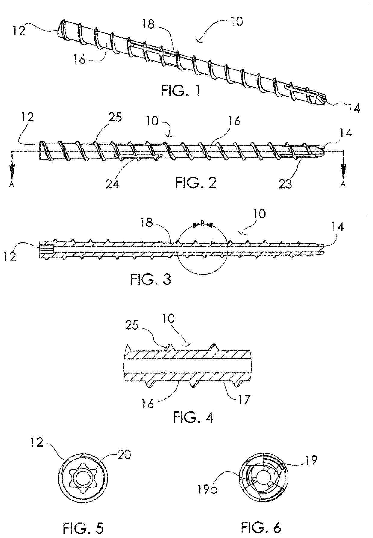
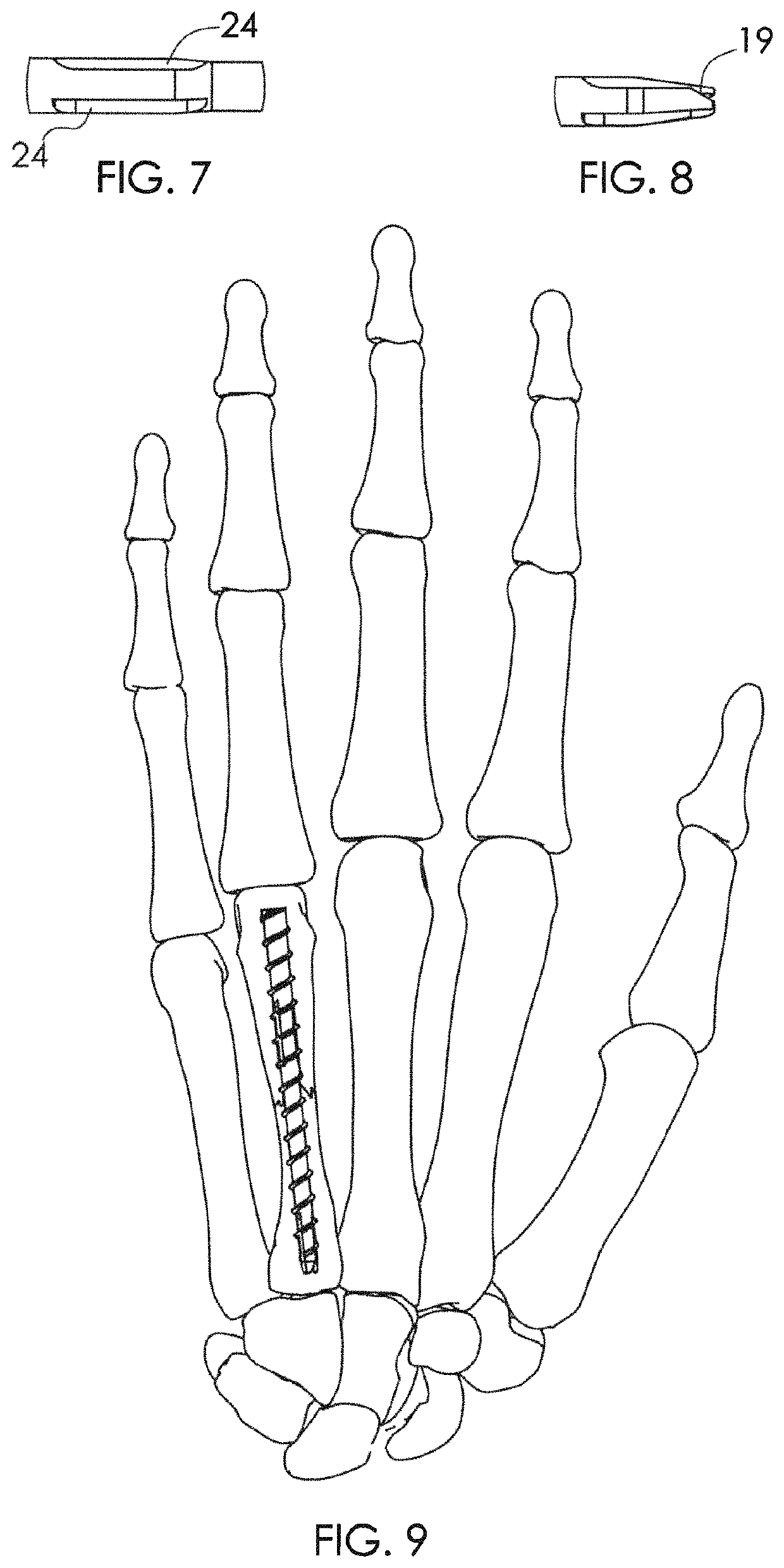
[0041]FIG. 1 shows an exemplary embodiment 10 of the threaded intramedullary nail of the present invention. The nail 10 may be formed of any suitable biocompatible material, such as surgical grade stainless steel, titanium, alloys of nickel and chromium, nitinol, PEEK, hydroxyapatite, bio-glass or other bio compatible materials or combinations of these materials. The nail 10 has a first end, or proximal end, 12, a second end, or distal end, 14, a shaft 16 with an outer surface 17, and a center portion 18 between first end 12 and second end 14. A cutting end 19 with a bevel and two, three or four teeth 19a is provided at the trailing end 14 (which is distal relative to the torque driving recess but is implanted in the proximal portion of the metacarpal) and a driving surface 20 in a drive recess 22 is formed in the top of first end 12.

[0042]The cutting point 19 helps to cut through any bone left behind when the bone is drilled to receive device 10, and further include 2-5 equally rad...


PUM


Abstract

The present invention relates to a device and system for fixation of intra-articular and extra-articular fractures and non-unions of small bones and other small bone fragments, and more particularly to a threaded nail with a robust length and a trailing end with a cutting tip and longitudinal cutting flutes and a stepped diameter with cutting flutes at the transition point, and an optional cannulation along the central longitudinal axis of the nail.

Description

INCORPORATION BY REFERENCE TO ANY PRIORITY APPLICATIONS[0001]Any and all applications for which a foreign or domestic priority claim is identified in the Application Data Sheet as filed with the present application are hereby incorporated by reference under 37 CFR 1.57.[0002]This application is a continuation of International Patent Application No. PCT / US2018 / 049342, filed Sep. 4, 2018, entitled INTRAMEDULLARY THREADED NAIL FOR RADIAL CORTICAL FIXATION, which claims the benefit of priority to U.S. Provisional Patent Application No. 62 / 554,123, filed Sep. 5, 2017, entitled INTRAMEDULLARY THREADED NAIL, the entirety of which is hereby incorporated by reference herein and should be considered part of this specification.FIELD OF THE INVENTION[0003]The present invention relates to a device and system for fixation of fractures and non-unions of small bones and other small bone fragments, and more particularly to a threaded nail with a robust length and a headless leading end with a torque...

Claims


Application Information

Patent Timeline
Patent Type & Authority Patents(United States)
IPC IPC(8): A61B17/72A61B17/86A61B17/00
CPCA61B17/7291A61B17/864A61B17/8635A61B17/8645A61B2017/00867
Inventor CHAMPAGNE, LLOYD P.ZOLDOS, JOZEFBRIGANTI, RICHARD T.LEITHER, ANDREW J.
Owner EXSOMED CORP
Why Eureka
Try Eureka