Radiation imaging apparatus
a technology of imaging apparatus and sonic wave, which is applied in the direction of radioation controlled devices, television systems, instruments, etc., can solve the problems of increased power consumption during imaging, uneven images, and increased functionalities, and achieves good holdability and less discomfor
- Summary
- Abstract
- Description
- Claims
- Application Information
AI Technical Summary
Benefits of technology
Problems solved by technology
Method used
Image
Examples
embodiment 1
Configuration of Radiation Imaging System
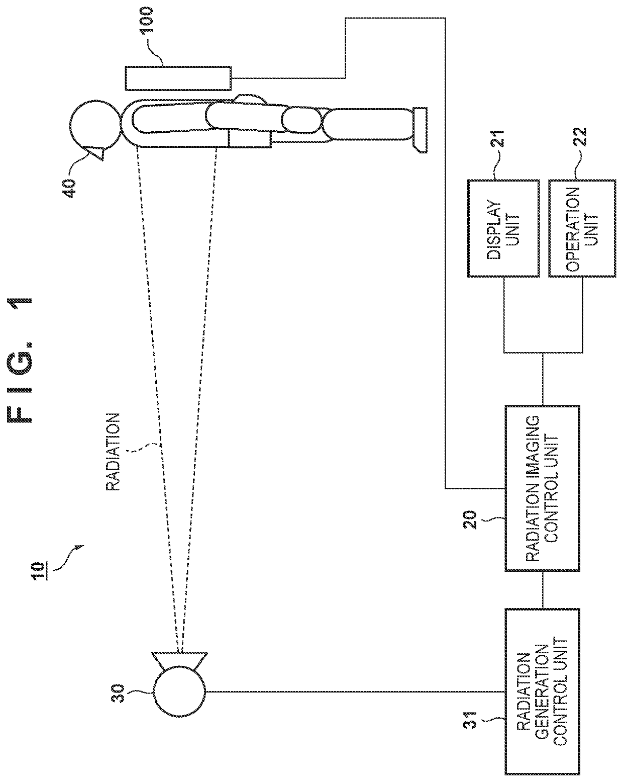
[0016]FIG. 1 shows an example configuration of a radiation imaging system 10 according to Embodiment 1. The radiation imaging system 10 is a system for imaging a digital radiation image (hereinafter referred to as “radiographic image”), and performs examination (imaging) based on an examination order, which includes a plurality of pieces of examination information. The examination information includes imaging protocol information, and imaging protocols defines parameter information or imaging implementation information to be used during imaging or in image processing, as well as imaging environment information, such as a sensor type or an imaging orientation. The examination information includes information that specifies an examination order or specifies a radiographic image according to the examination order, such as an examination ID and a receipt number.
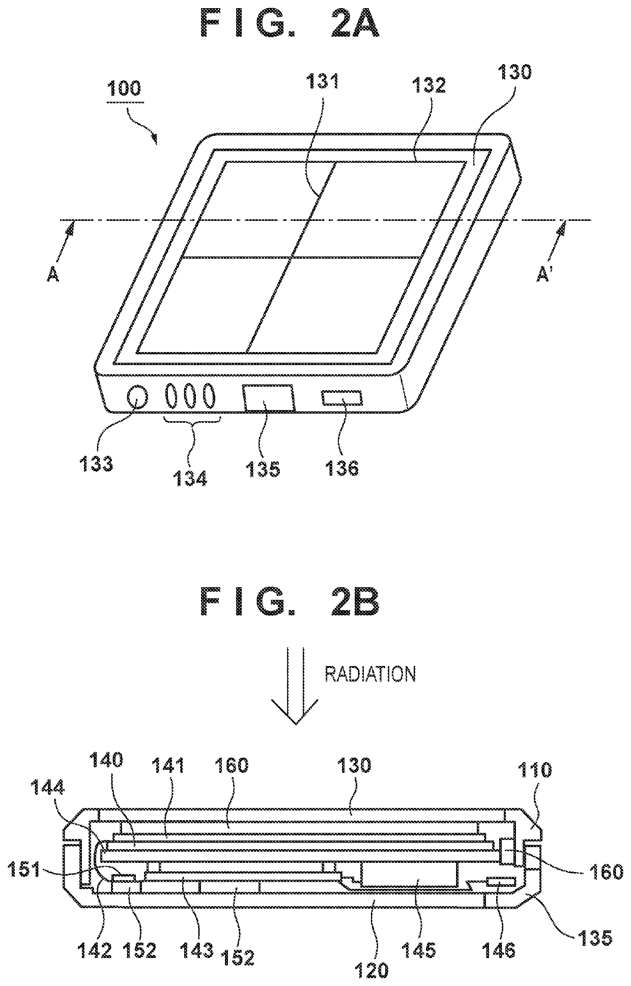
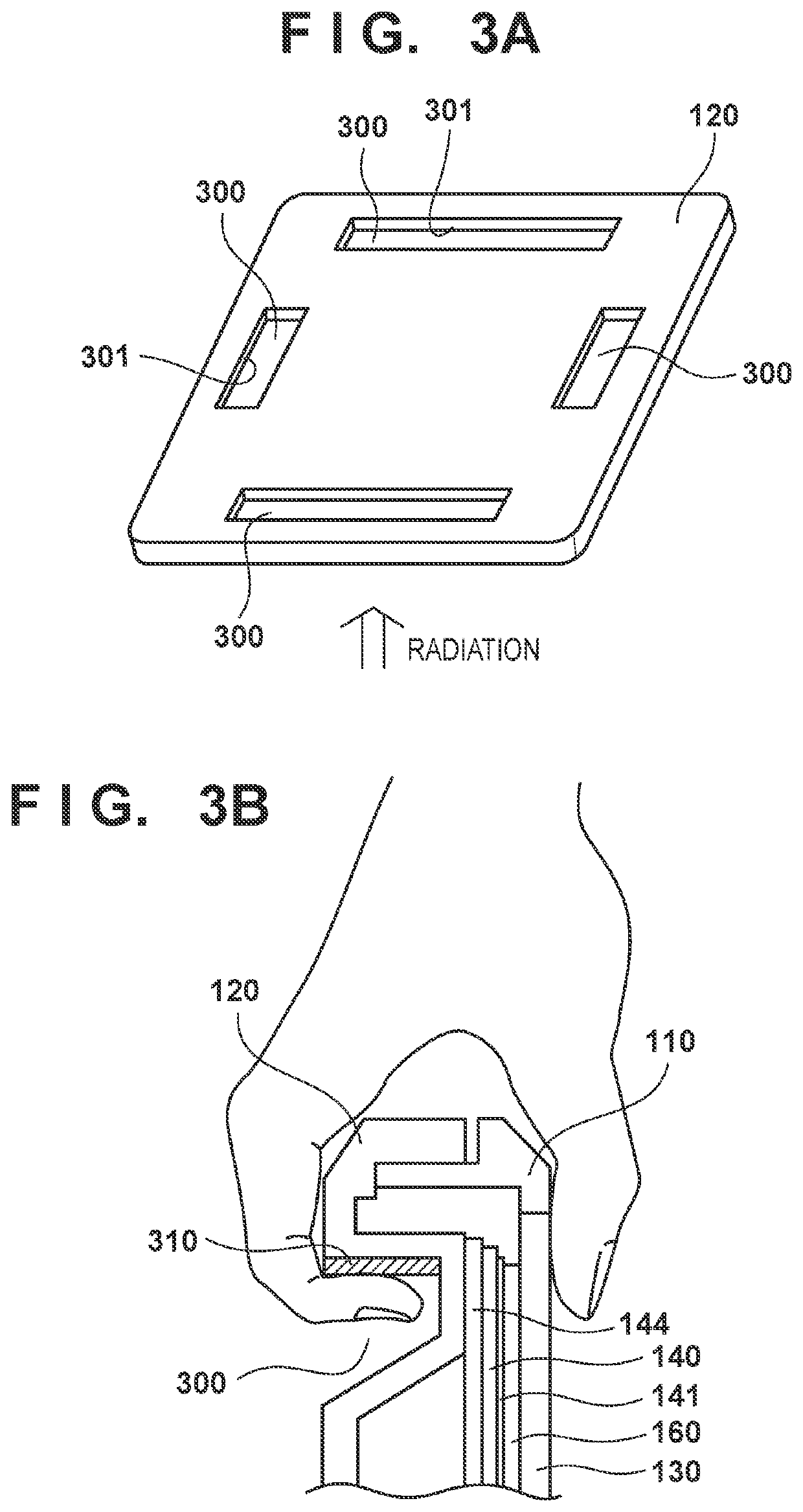
[0017]The radiation imaging system 10 includes a radiation imaging apparatus 100, a ra...
embodiment 2
[0028]This embodiment will describe a structural example of a holding portion that has better holdability than that in Embodiment 1 and can lessen discomfort when being handled. Differences from Embodiment 1 will be described below. FIGS. 4A and 4B show a structure of holding portions provided in the back face of the radiation imaging apparatus 100 according to this embodiment. FIG. 4A is a perspective view as viewed from the back face of the radiation imaging apparatus 100, and FIG. 4B is a schematic cross-sectional view that illustrates a cross-sectional structure of a holding portion.
[0029]In this embodiment, to form holding faces 401 of recesses to be held in an exterior housing of the radiation imaging apparatus 100, holding components 410 are used as predetermined holding portion forming components that are made of a material with a lower heat conductivity than that of the rear housing 120. The holding components 410 may be made of a material such as a resin or a rubber, which...
embodiment 3
[0032]This embodiment will describe a relationship between the constituent elements of the radiation imaging apparatus 100 in a structure in which holding components are provided. FIGS. 5A and 5B show a structural example of the holding portions provided in the back face of the radiation imaging apparatus 100 according to this embodiment. FIG. 5A is a perspective view as viewed from the back face of the radiation imaging apparatus 100, and FIG. 5B is a schematic cross-sectional view that illustrates a cross-sectional structure of a holding portion.
[0033]In this embodiment, recesses to be held are formed in an exterior housing of the radiation imaging apparatus 100, using holding components 530. The holding components 530 are fixed via heat insulating double-sided tapes 540 so as to be fitted to open-hole portions that are provided in the rear housing 120. The holding components 530 may be made of a resin, a rubber material, or the like, as mentioned in Embodiment 2. That is to say, ...
PUM
| Property | Measurement | Unit |
|---|---|---|
| angle | aaaaa | aaaaa |
| thickness | aaaaa | aaaaa |
| depth | aaaaa | aaaaa |
Abstract
Description
Claims
Application Information
 - R&D
- Intellectual Property
- Life Sciences
- Materials
- Tech Scout
- Unparalleled Data Quality
- Higher Quality Content
- 60% Fewer Hallucinations
Browse by: Latest US Patents, China's latest patents, Technical Efficacy Thesaurus, Application Domain, Technology Topic, Popular Technical Reports.
© 2025 PatSnap. All rights reserved.Legal|Privacy policy|Modern Slavery Act Transparency Statement|Sitemap|About US| Contact US: help@patsnap.com


