Ultrasonic welding device

Active Publication Date: 2022-01-18
SCHUNK SONOSYST
View PDF10 Cites 0 Cited by
  • Summary
  • Abstract
  • Description
  • Claims
  • Application Information

AI Technical Summary

Benefits of technology

The invention is an ultrasonic welding device that can hold the anvil in place even when the normal forces are small. This is achieved by using a surface structure formed by a line grid with raised grid lines of a specific height. This structure helps to prevent relative movement between the anvil and the sonotrode, which improves the quality and efficiency of ultrasonic welding.

Problems solved by technology

If such relative movements were to occur, they could otherwise lead to local welds between the anvil and the anvil carrier in the connection plane, which would preclude being able to separate the anvil from the anvil carrier when the anvil needs to be exchanged.
It has emerged in practice that when the anvil is miniaturized and the screw connection between the anvil and the anvil carrier is correspondingly small, it is not possible to generate a sufficiently large pretensioning force between the anvil and the anvil carrier in order to ensure suppressing the undesirable relative movement between the anvil and the anvil carrier.

Method used


Image

  • Ultrasonic welding device
  • Ultrasonic welding device
  • Ultrasonic welding device

Examples


Embodiment Construction

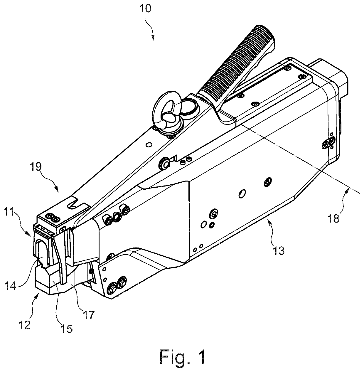
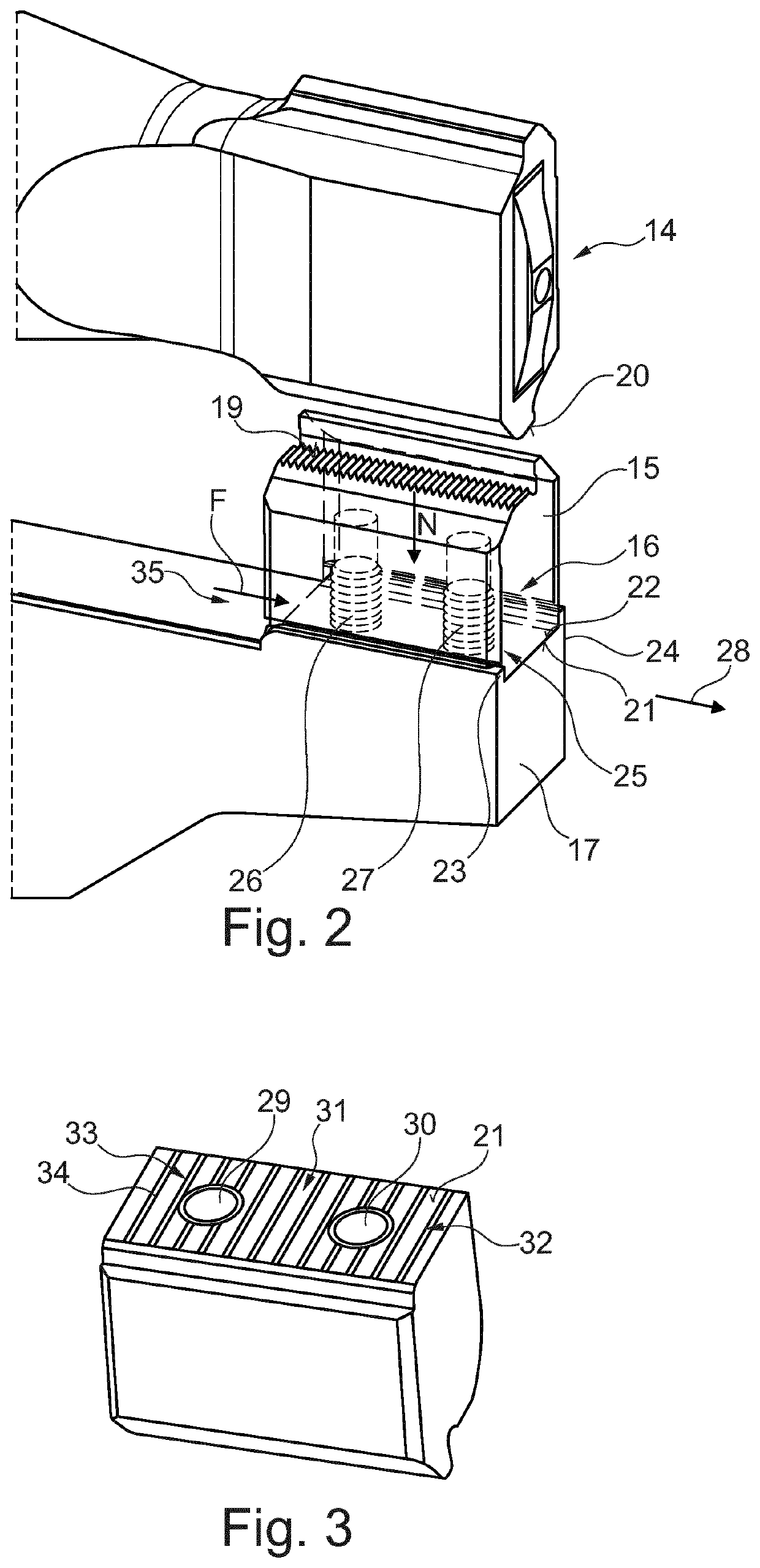
[0023]FIG. 1 shows in an isometric view an ultrasonic welding device 10 realized as a pair of ultrasonic welding tongs and having an upper tong part 11 and a lower tong part 12 which are disposed in a shared tong casing 13. As an essential component, upper tong part 11 comprises an ultrasonic vibration device comprising a sonotrode 14 which is disposed on a front end of the ultrasonic vibration device and forms a first welding jaw. On welding casing 13, an anvil 15 is disposed which is held displaceably vis-à-vis sonotrode 14 and is connected to an anvil carrier 17 in an exchangeable manner by means of a pretensioning device realized as screw connection 16 (FIG. 2) in this instance.

[0024]Anvil 15 forms a second welding jaw which can be pivoted against sonotrode 14 around a pivot axis 18 formed in the back part of tong casing 13 by means of an actuating device (not shown) in such a manner that an opposing surface 19 formed on anvil 15 is moved against a work surface 20 of sonotrode 1...


PUM

PropertyMeasurementUnit
Lengthaaaaaaaaaa
Lengthaaaaaaaaaa
Lengthaaaaaaaaaa

Abstract

The invention relates to an ultrasonic welding device comprising a sonotrode (14) transmitting ultrasonic vibrations and an anvil (15) disposed on an anvil carrier (17), the anvil (15) being disposed on the anvil carrier (17) in an exchangeable manner so that an mounting surface (21) of the anvil (15) rests against a support surface (22) of the anvil carrier (17) by means of a normal force exerted by a pretensioning device, the mounting surface (21) of the anvil (15) having a surface hardness greater than the surface hardness of the support surface (22) of the anvil carrier (17), the mounting surface (21) having a surface structure at least in the area of a partial surface, and the mounting surface (21) having a surface roughness of Rz / Ra≥2 at least in the area of the partial surface.

Description

FIELD OF THE INVENTION[0001]The invention relates to an ultrasonic welding device comprising a sonotrode transmitting ultrasonic vibrations and an anvil disposed on an anvil carrier, the anvil being disposed on the anvil carrier in an exchangeable manner so that an mounting surface of the anvil rests against a support surface of the anvil carrier by means of a normal force exerted by a pretensioning device.BACKGROUND OF THE INVENTION[0002]From product brochure “STAPLA Ultraschall-Schweißsysteme KOBRA” [English: “STAPLA Ultrasonic Welding Systems KOBRA”] by Schunk Sonosystems GmbH published August 2007, an ultrasonic welding device of the make mentioned above is known. The familiar ultrasonic welding device realized as a pair of welding tongs comprises an anvil which is disposed on an anvil carrier in an exchangeable manner and is held in position in a connection plane between an mounting surface of the anvil and a support surface of the anvil carrier by means of a screw connection, ...

Claims


Application Information

Patent Timeline
IPC IPC(8): B32B37/00B29C65/00B23K20/10B29C65/08
CPCB29C66/8167B23K20/10B29C65/08B29C66/81264B29C66/81265B23K37/04B29C66/81433H01R43/0207B23K20/106
Inventor MUELLER, STEFANWAGENBACH, RAINERWERNER, WALDEMAR
Owner SCHUNK SONOSYST
Why Eureka
Try Eureka