Method and control unit for operating a braking system and braking system

a braking system and control unit technology, applied in the direction of braking systems, vehicle sub-unit features, braking components, etc., can solve the problems of no longer being able to correctly evaluate the hydraulic volume, no longer being able to operate the braking action, and being subject to a certain leakage, etc., to achieve simple and reliable leakage detection, maintain driving stability, and improve the effect of reliability

Active Publication Date: 2022-01-25
ROBERT BOSCH GMBH
View PDF5 Cites 0 Cited by
  • Summary
  • Abstract
  • Description
  • Claims
  • Application Information

AI Technical Summary

Benefits of technology

[0005]An example method according to the present invention may have the advantage that the leakage is precisely ascertainable even while an, in particular, dynamic braking action is carried out, which is carried out or impaired in an automated manner, for example, by activating the motor vehicle to maintain the driving stability. This results in a higher reliability against failure of the braking system since a critical leakage is promptly and precisely detectable. According to the present invention, it is provided for this purpose that the leakage is ascertained as a function of the ascertained hydraulic volume and as a function of an actuation of the valve. By taking the valve actuation into consideration in the computation of the leakage, it is achieved that the oscillations in the braking system which occur during the valve actuation and the volume losses caused by the actuation of, in particular, a discharge valve are detected and included in the ascertainment of the actual undesirable leakage in the braking system. In this way, an intended leakage, which takes place by the actuation of, in particular, a discharge valve, in the overall volume changes of the brake fluid in the braking system may be subtracted to obtain the undesirable leakage. As a result, a simple and reliable ascertainment of the leakage in the braking system is also ensured during an active brake intervention or operation.
[0011]Furthermore, the volume loss is preferably ascertained individually for each wheel brake of the motor vehicle, and an overall volume loss is computed from the ascertained volume losses and used as a basis for the determination of the leakage. In this way, the overall leakage of the braking system is established in a simple manner. Advantageously, the motor vehicle includes multiple wheel brakes, preferably a particular wheel brake being assigned to each wheel of the motor vehicle.
[0018]Preferably, a sensor signal of a pressure sensor of the sensor system detecting the hydraulic pressure is filtered, in particular as a function of an instantaneous operating state of the braking system. Due to the time differentiation, the high-frequency components in the signal chain are amplified, the largest interference being visible in the pressure signal. The interference results, on the one hand, from the sensor noise of the pressure sensor itself and, on the other hand, from the switching processes of the discharge valve or discharge valves and the pressure waves impressed thereby. In the assumption that these frequencies are far off the “permanently” present leakage of the braking system, the useful signal is extracted with the aid of the preferred filtering. Selecting the filtering as a function of the instantaneous operating state results in a precise determination of the leakage. Preferably, a PT1 filter is used for filtering, in particular having a variable filter constant.
[0019]In particular, the sensor signal is filtered as a function of an instantaneous hydraulic pressure and a hydraulic pressure change, so that an advantageous useful signal is provided.

Problems solved by technology

Braking systems, however, are usually subject to a certain leakage, as a result of which brake fluid is lost over time and therefore may no longer be available for a braking action.
However, if a dynamic braking action is carried out, in which, for example, the hydraulic pressure is reduced or a hydraulic volume is released from the particular brake circuit by the actuation of a valve assigned to a wheel brake to quickly reduce the braking force, as is practiced in ABS systems, for example, it is no longer readily possible to correctly evaluate the hydraulic volume.
This results in difficulties in exactly determining the existing leakage with the aid of conventional methods.
When a leakage occurs, the actual volume differs from the setpoint volume, so that the actual volume is lower at the actually set setpoint volume and, as a result, the desired braking force cannot be achieved.
The interference results, on the one hand, from the sensor noise of the pressure sensor itself and, on the other hand, from the switching processes of the discharge valve or discharge valves and the pressure waves impressed thereby.

Method used


Image

  • Method and control unit for operating a braking system and braking system
  • Method and control unit for operating a braking system and braking system
  • Method and control unit for operating a braking system and braking system

Examples


Embodiment Construction

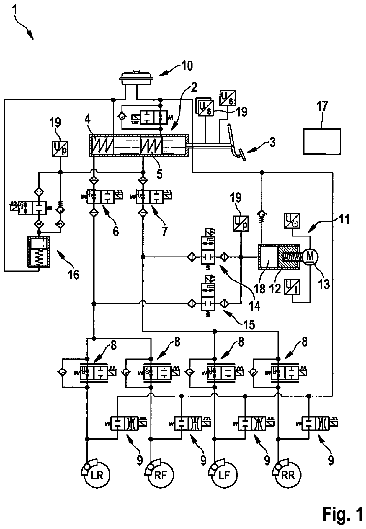
[0027]FIG. 1 shows, in a simplified illustration, an advantageous braking system 1 of a motor vehicle which is not shown in greater detail here. Braking system 1 is designed as a hydraulically operating braking system and includes multiple wheel brakes LR, RF, LF and RR, which are each assigned to a wheel of the motor vehicle and are hydraulically actuatable. For this purpose, braking system 1 includes a master brake cylinder 2, which is actuatable by a driver of the motor vehicle with the aid of a brake pedal 3. In the present example, master brake cylinder 2 is designed as a tandem cylinder including two hydraulic chambers 4 and 5, a design of the braking system including a single master brake cylinder also being possible. Hydraulic chambers 4, 5 are each hydraulically connectable by a switching valve 6, 7 to a pair of wheel brakes LR, RF and LF, RR, respectively. In the present example, wheel brakes LR and RF are connectable to switching valve 6, and wheel brakes LF and RR are co...


PUM


Abstract

A method for ascertaining a leakage in a hydraulic braking system of a motor vehicle, the braking system including at least one hydraulically actuatable wheel brake, at least one pressure generator and at least one discharge valve which is assigned to the wheel brake and actuated as a function of a driving situation of the motor vehicle to maintain driving stability, and a hydraulic volume of the braking system being monitored. It is provided that the leakage is ascertained as a function of the ascertained hydraulic volume and as a function of an actuation of the discharge valve.

Description

CROSS REFERENCE[0001]The present application claims the benefit under 35 U.S.C. § 119 of German Patent Application No. DE 102018212848.0 filed on Aug. 1, 2018, which is expressly incorporated herein by reference in its entirety.FIELD[0002]The present invention relates to a method for ascertaining a leakage in a hydraulic braking system of a motor vehicle, the braking system including at least one hydraulically actuatable wheel brake, at least one pressure generator and at least one discharge valve which is assigned to the wheel brake and actuated as a function of a driving situation of the motor vehicle to maintain driving stability, and a hydraulic volume of the braking system being monitored.[0003]The present invention furthermore relates to a control unit which is specifically configured to carry out the above-mentioned method, and to a braking system including such a control unit.BACKGROUND INFORMATION[0004]To be able to ensure the functional capability of a hydraulic braking sy...

Claims


Application Information

Patent Timeline
Patent Type & Authority Patents(United States)
IPC IPC(8): B60T17/22B60T13/16B60T7/12B60T8/1755
CPCB60T17/221B60T7/12B60T8/1755B60T13/167B60T2270/306B60T2270/86B60T17/22B60T2270/403B60T2270/406B60T13/686B60Y2400/81B60Y2400/301
Inventor HENNING, WADIM
Owner ROBERT BOSCH GMBH
Why Eureka
Try Eureka