
Method for processing a signal from a coherent lidar in order to reduce noise and related lidar system

a lidar and signal processing technology, applied in the field of coherent lidars, can solve the problems of reducing the sensitivity of the lidar, reducing the power, and reducing the intensity

Active Publication Date: 2022-02-08
THALES SA
View PDF4 Cites 0 Cited by
  • Summary
  • Abstract
  • Description
  • Claims
  • Application Information

AI Technical Summary

Benefits of technology

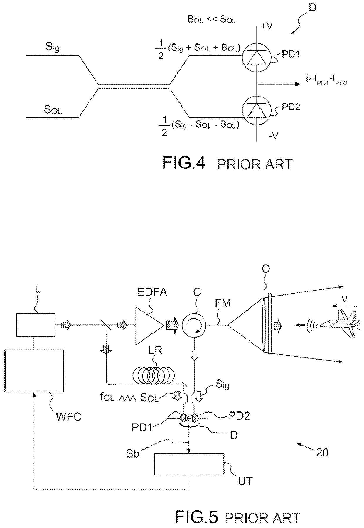
The invention provides a way to reduce the noise caused by the detection of a local-oscillator signal in a balanced detector used in coherent lidar. This method can be applied to any type of coherent lidar system. By decreasing this noise, the invention improves the quality of the sensor's signal and makes it easier to detect objects or people in the surrounding environment.

Problems solved by technology

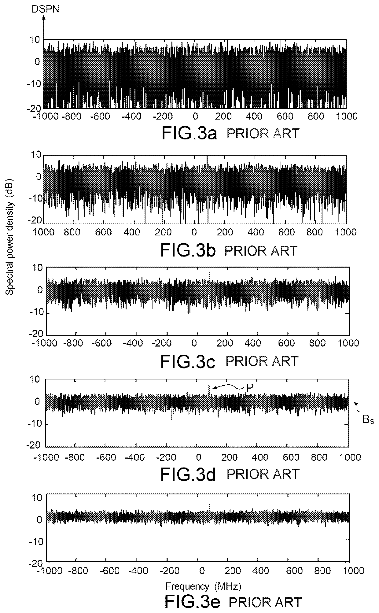
One way of limiting photonic shot noise is to limit the power of the local oscillator but this also decreases the sensitivity of the lidar, because decreasing the power also decreases the intensity of the peaks.
This noise is a result of spontaneous emission and of exterior disruptions to the laser cavity.

Method used


Image

  • Method for processing a signal from a coherent lidar in order to reduce noise and related lidar system
  • Method for processing a signal from a coherent lidar in order to reduce noise and related lidar system
  • Method for processing a signal from a coherent lidar in order to reduce noise and related lidar system

Examples


Embodiment Construction

[0083]Before describing the invention we will recall certain mathematical concepts known to those skilled in the art and required for a good comprehension of the invention.

[0084]The Fourier transform FT of a time-dependent function S(t) is defined, e.g. transform to the frequency domain:

FT[S(t)]=∫−∞+α1S(t).exp(−2iπvt)dt

[0085]The product of convolution of two complex time-dependent functions S1(t) and S2(t) is defined as:

S1*S2=∫−∞+∞S1(τ).S*2(t−τ)dτFT[S1(t)*S2(t)]=FT[S1(t)].FT[S2(t)]

[0086]S being a complex number:

S=Re(S)+iIm(S) and S*=Re(S)−iIm(S)

[0087]The cross-correlation function of S1 and S2 is also defined:

CS1S2=S1(t)⊗S2(t)=∫−∞+∞S1(t).S*2(t−τ)dt=∫−∞+∞S1(t+τ).S*2(t)dt   (1)

and its Fourier transform:

FT[CS1S2(τ)]=FT[S1(t)*S*2(−t)]=FT[S1(t)]×FT[S*2(−t)]=FT[S1(t)]×{FT[S2(t]}*   (2)

[0088]The correlation function is maximum when S1 and S2 are identical to within a time shift. CS1S2 is then maximum for a value of τo corresponding to this shift.

[0089]The method 80 for processing a signal...


PUM


Abstract

A method for processing a signal from a coherent lidar includes a coherent source, the method comprising steps consisting of: generating a first beat signal and a second beat signal, using respectively a first detection assembly and a second detection assembly for a plurality of n time intervals, determining n respective values of spectral density using a transform in the frequency domain of the cross-correlation between the first and second beat signals, determining a mean value of the spectral density using said n values of spectral density, determining a piece of location information on the target using the mean value of said spectral density.

Description

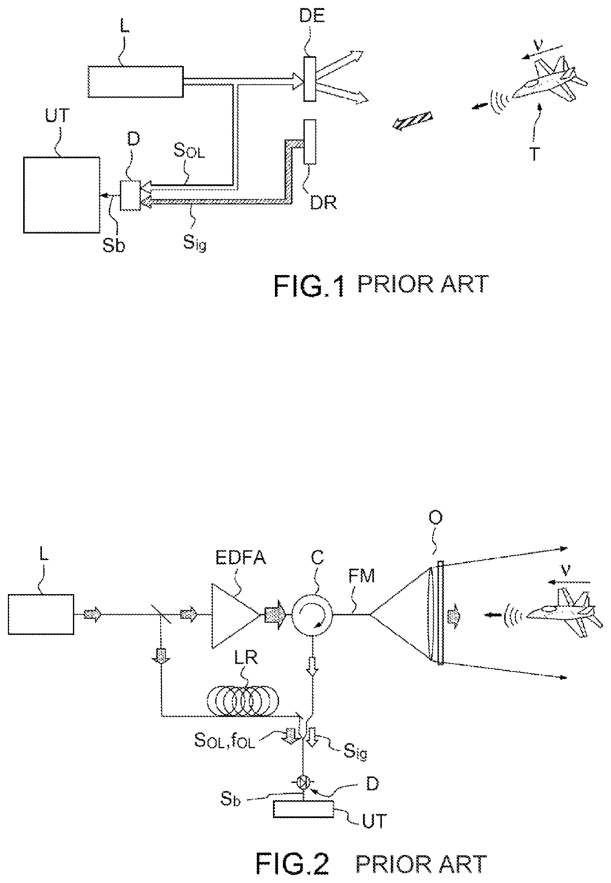
CROSS-REFERENCE TO RELATED APPLICATIONS[0001]This application is a National Stage of International patent application PCT / EP2017 / 084754, filed on Dec. 28, 2017, which claims priority to foreign French patent application No. FR 1601875, filed on Dec. 27, 2016, the disclosures of which are incorporated by reference in their entirety.FIELD OF THE INVENTION[0002]The invention relates to the field of coherent lidars.BACKGROUND[0003]The principle of a coherent lidar is well-known in the prior art and illustrated in FIG. 1. A coherent lidar comprises a coherent source L, typically a laser, that emits a coherent light wave (IR, visible or near-UV domain), an emitting device DE that allows a volume of space to be illuminated, and a receiving device DR, which collects a fraction of the light wave backscattered by a target T. The Doppler frequency shift νDop of the backscattered wave depends on the radial velocity v of the target T:νDop=2v / λλ wavelength of the laser[0004]On reception, the rece...

Claims


Application Information

Patent Timeline
Patent Type & Authority Patents(United States)
IPC IPC(8): G01C3/08G01S17/34G01S7/481G01S7/4913G01S7/4915
CPCG01S17/34G01S7/4818G01S7/4913G01S7/4915
Inventor PILLET, GRÉGOIREFENEYROU, PATRICK
Owner THALES SA
Learn More