A Miniaturized Rubidium Frequency Standard Physical System

A Physical System, Rubidium Frequency Standard Technology

Active Publication Date: 2021-05-28
WUHAN INST OF PHYSICS & MATHEMATICS CHINESE ACADEMY OF SCI
View PDF5 Cites 0 Cited by
  • Summary
  • Abstract
  • Description
  • Claims
  • Application Information

AI Technical Summary

Problems solved by technology

On the other hand, since the spectral light emission includes 87 The Rb atom emits light and the buffer gas atom emits light, which contributes to the transition signal is 87 The effective light emitted by Rb atoms, the spectrum emitted by Xe atoms has no pumping effect, does not contribute to the atomic signal, and only increases the shot noise after being detected by the photocell, which limits the performance of the physical system.

Method used


Image

  • A Miniaturized Rubidium Frequency Standard Physical System
  • A Miniaturized Rubidium Frequency Standard Physical System
  • A Miniaturized Rubidium Frequency Standard Physical System

Examples


Embodiment 1

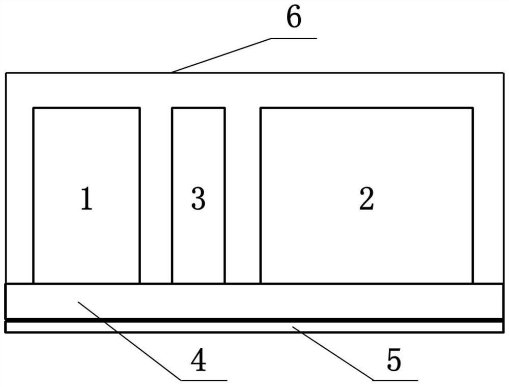
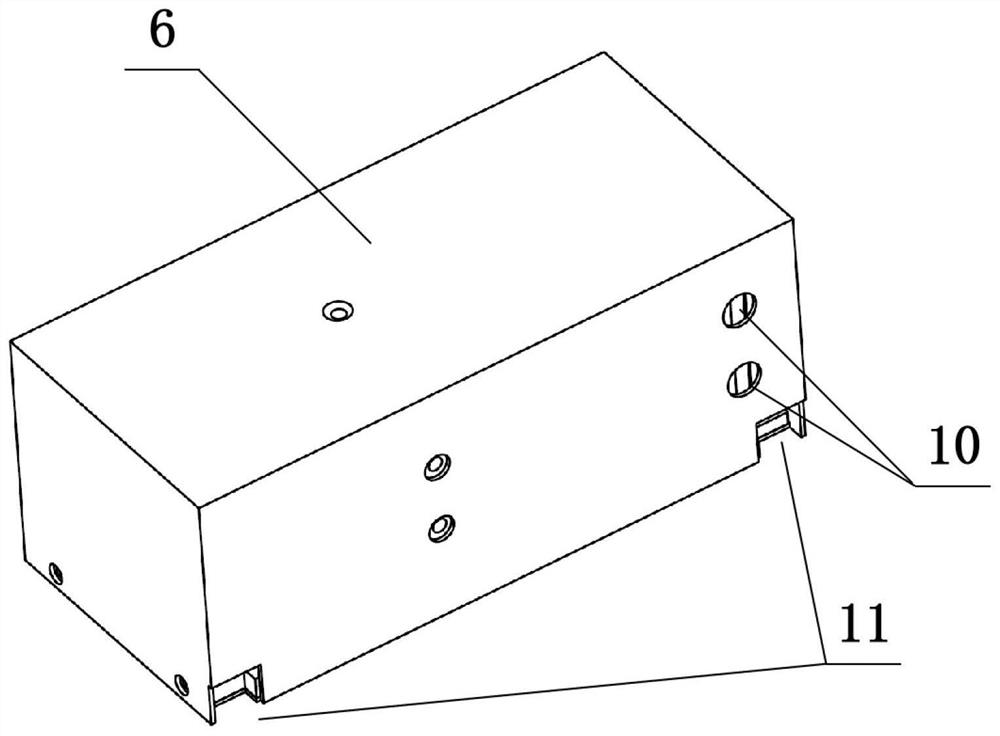
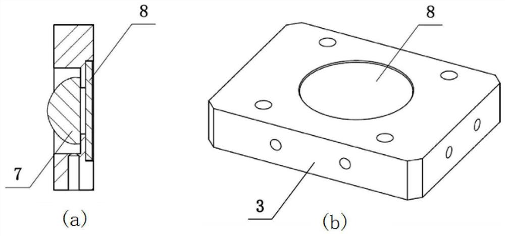
[0032] Such as Figure 5 As shown, a miniaturized rubidium frequency standard physical system includes a rubidium spectrum lamp 1, a cavity bubble system 2, an optical heat insulation bracket 3, a heat insulation bottom plate 4, a magnetic shield bottom plate 5, a magnetic shield shell 6, a plano-convex lens 7 and an interference Filter 8.

[0033] The rubidium spectrum lamp 1 and the cavity bubble system 2 are respectively fixed on the heat insulation base plate 4 through four M2 screws at the bottom, and the optical heat insulation bracket 3 is connected with the waist-shaped slot hole 9 on the heat insulation base plate 4 through two M2 screws. The heat insulation bracket 3 is located between the rubidium spectrum lamp 1 and the cavity bubble system 2, and the waist-shaped slot 9 makes the distance between the optical heat insulation bracket 3 relative to the rubidium spectrum lamp 1 and the cavity bubble system 2 adjustable.

[0034] The two sides of the optical heat-insu...

Embodiment 2

[0040] Such as Figure 5As shown, a miniaturized rubidium frequency standard physical system includes a rubidium spectrum lamp 1, a cavity bubble system 2, an optical heat insulation bracket 3, a heat insulation bottom plate 4, a magnetic shield bottom plate 5, a magnetic shield shell 6, a plano-convex lens 7 and an interference Filter 8.

[0041] The rubidium spectrum lamp 1 and the cavity bubble system 2 are respectively fixed on the heat insulation base plate 4 through four M2 screws at the bottom, and the optical heat insulation bracket 3 is connected with the waist-shaped slot hole 9 on the heat insulation base plate 4 through two M2 screws. The heat insulation bracket 3 is located between the rubidium spectrum lamp 1 and the cavity bubble system 2, and the waist-shaped slot 9 makes the distance between the optical heat insulation bracket 3 relative to the rubidium spectrum lamp 1 and the cavity bubble system 2 adjustable.

[0042] The two sides of the optical heat-insul...


PUM


Abstract

The invention discloses a miniaturized rubidium frequency standard physical system, which includes a rubidium spectrum lamp and a cavity bubble system, the rubidium spectrum lamp and the cavity bubble system are respectively fixed on a heat-insulating base plate, and the optical heat-insulating bracket is connected to the heat-insulating base plate through bracket fixing screws The waist-shaped slot hole on the top is connected, and the optical heat insulation bracket is located between the rubidium spectrum lamp and the cavity bubble system. The two sides of the optical heat insulation bracket are respectively provided with connected plano-convex lens mounting holes and filter mounting holes, and plano-convex lens mounting holes. A plano-convex lens is installed inside, an interference filter is installed in the filter installation hole, the magnetic shield bottom plate is set on the bottom surface of the heat insulation bottom plate, the rubidium spectrum lamp, the cavity bubble system, and the optical heat insulation bracket are set in the magnetic shield shell, and the magnetic shield The screen shell is buckled upside down on the heat insulation bottom plate. The invention has the advantages of simple assembly, adjustable parameters and convenient mass production, and can be used for modular production of miniaturized rubidium frequency standard physical systems.

Description

technical field [0001] The invention relates to a physical system structure, in particular to a miniaturized rubidium frequency standard physical system, which is suitable for use in miniaturized rubidium frequency standards with strict volume requirements. Background technique [0002] Due to its small size, low power consumption, light weight and other characteristics, its practicability far exceeds other types of atomic frequency standards, and it has become the most widely used atomic frequency standard. It mainly has two development directions: high performance and miniaturization . High-performance rubidium frequency standards are mainly mounted on navigation satellites, synthetic aperture radar satellites, electronic reconnaissance satellites, military communication satellites, etc. Miniaturized rubidium frequency standards are widely used in communication base stations, airborne and missile-borne equipment, and field operations And low-orbit small satellites and oth...

Claims


Application Information

Patent Timeline
Patent Type & Authority Patents(China)
IPC IPC(8): H03L7/26
CPCH03L7/26
Inventor 王晨王鹏飞赵峰梅刚华
Owner WUHAN INST OF PHYSICS & MATHEMATICS CHINESE ACADEMY OF SCI
Why Eureka
Try Eureka