
Four stroke relative motion cylinder with dedicated compression space

a relative motion and compression space technology, applied in the field of mechanical devices, can solve the problems of reducing the overall economy of the engine and vehicle in which such enlarged cylinders are used, the limited efficiency of recovery systems is often increased, and the limited efficiency of cylinder-based systems is further compounded. , to achieve the effect of reducing the vibration caused by initial forces

Active Publication Date: 2022-02-15
HANNA IBRAHIM
View PDF16 Cites 1 Cited by
  • Summary
  • Abstract
  • Description
  • Claims
  • Application Information

AI Technical Summary

Benefits of technology

The patent describes a device that reduces the amount of fluid that enters a machine during a stroke of the crankshaft piston. The device also reduces friction between the piston and cylinder, so that more power can be transferred during a power stroke. These improvements help to make the machine more efficient and effective.

Problems solved by technology

Increasing stroke volume and / or distance may stipulate an increase in cylinder dimensions and thus cylinder mass, however, reducing the overall economy of an engine and vehicle in which such enlarged cylinders are used.
Hydraulic cylinders, for example, may be coupled to a hydraulic or turbo charger or to an electrical recovery system, though such recovery systems frequently exhibit limited efficiencies (e.g., 20-30%) especially when they work against a high initial pressure around 1000 psi.
Moreover, the limited efficiency of cylinder-based systems is further compounded when considering the energy expended in producing the compressed fluids provided as input to a cylinder, such as the energy required to accumulate pressurized fluid for hydraulic cylinders, and the energy required to refine and transport combustible fuel for combustion cylinders.
Direct injection engine methods have been implemented for the purpose of satisfying clean environment requirements, but it has become more challenging to satisfy such requirements.
Two stroke engines, for example, which are desired for having lesser moving parts, are completely prohibited in certain areas due to their tendency of releasing excessive amounts of non-completely burned exhaust and it is also not energy effective due to losing compressed fluids before they enter into a next combustion phase.
Wankel rotary engines are favorable because they have less parts, but are limited in their energy output.
Fluid intake pathways in direct injection engines, suffer from buildup of unburned exhaust that may leak backward within the engine.
Further, releasing non-burned fluid causes pollution and is a waste of fuel.
Further, it is known that higher initial pressures in supercharged engines cause high temperatures and subsequent damage due to high temperatures.

Method used


Image

  • Four stroke relative motion cylinder with dedicated compression space
  • Four stroke relative motion cylinder with dedicated compression space
  • Four stroke relative motion cylinder with dedicated compression space

Examples


Embodiment Construction

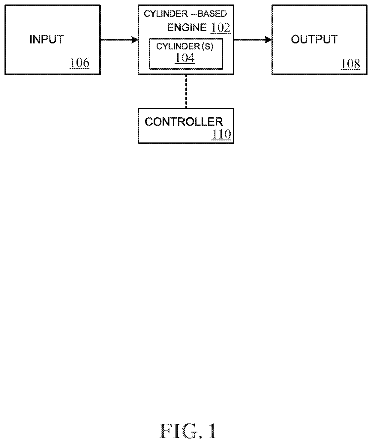
[0133]The following detailed description is merely exemplary in nature and is not intended to limit the described embodiments or the application and uses of the described embodiments. As used herein, the word “exemplary” or “illustrative” means “serving as an example, instance, or illustration.” Any implementation described herein as “exemplary” or “illustrative” is not necessarily to be construed as preferred or advantageous over other implementations. All of the implementations described below are exemplary implementations provided to enable persons skilled in the art to make or use the embodiments of the disclosure and are not intended to limit the scope of the disclosure, which is defined by the claims. Furthermore, there is no intention to be bound by any expressed or implied theory presented in the preceding technical field, background, brief summary or the following detailed description. It is also to be understood that the specific devices and processes illustrated in the at...


PUM


Abstract

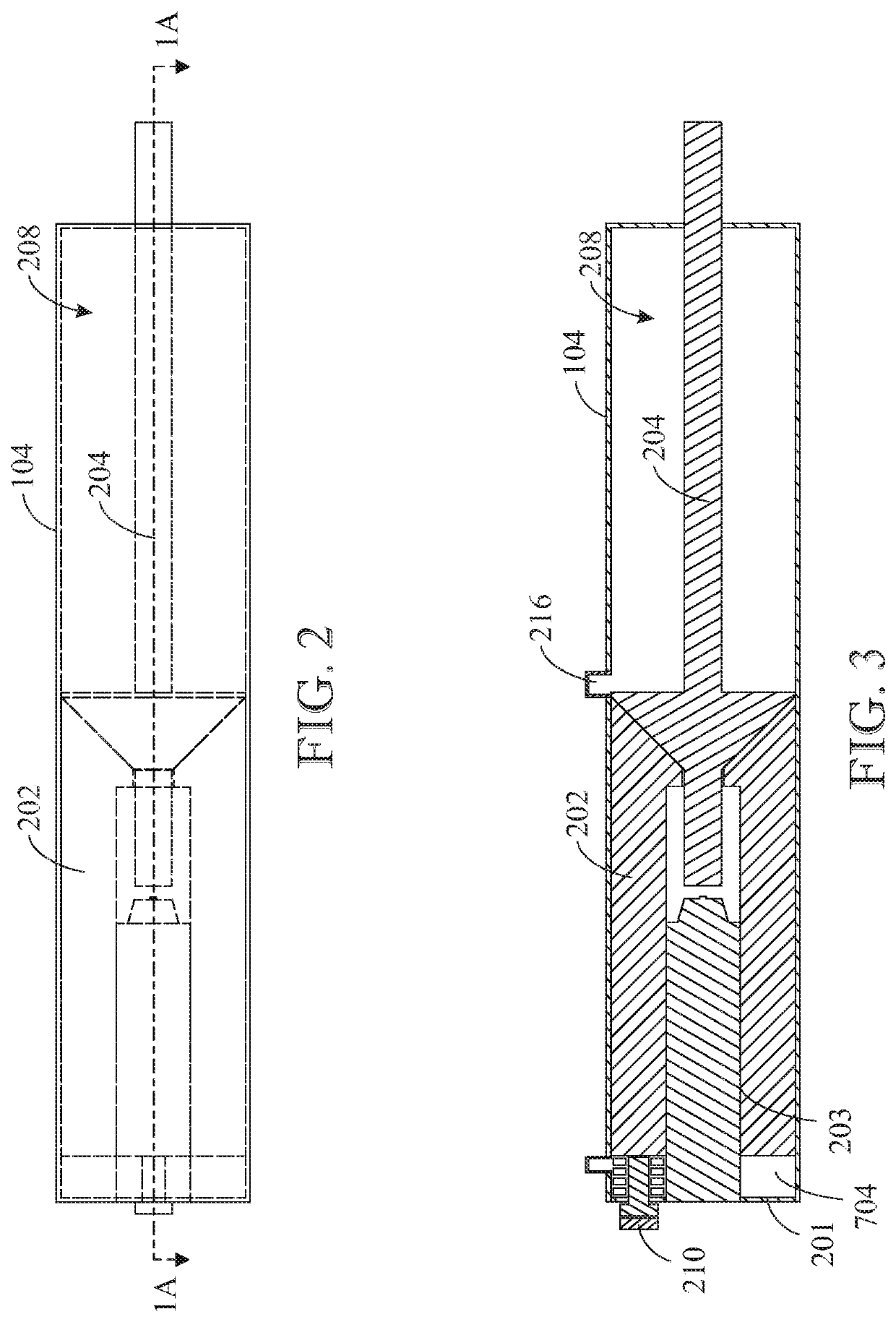
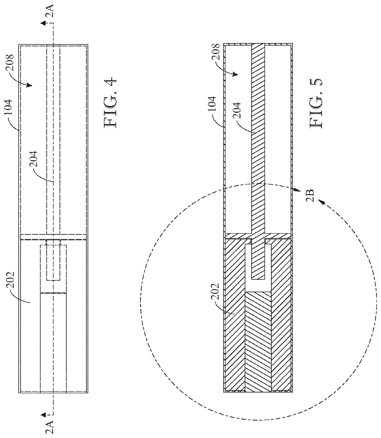
Implementations are disclosed herein that relate to a cylinder occupying structure. An example provides a cylinder system comprising a mechanical cylinder including an internal space in which a fluid is introduced, and a piston configured for reciprocating motion in the internal space, and a cylinder occupying structure including an insertion rod acting as a second piston, wherein the insertion rod is variably inserted into, and retracted from, the internal space of the cylinder in correspondence with the reciprocating motion of the piston and where parts of the insertion rod and the piston may surround the combustion space, and where fluid compression and fluid combustion is conducted within separate spaces.

Description

CROSS REFERENCE TO RELATED APPLICATIONS[0001]This U.S. non-provisional patent application is a continuation-in-part of co-pending U.S. non-provisional patent application Ser. No. 16 / 235,272, filed on Dec. 28, 2018, which is a continuation-in-part of U.S. non-provisional patent application Ser. No. 15 / 847,711 filed on Dec. 19, 2017 all of which are incorporated-by-reference herein in their entireties.FIELD OF THE INVENTION[0002]The present invention relates generally to mechanical devices used to perform work, and more particularly to hydraulic and combustion cylinders.BACKGROUND OF THE INVENTION[0003]A wide variety of devices utilize cylinders to perform mechanical functions and produce useful work. A typical internal combustion engine (ICE), for example, employs a number of cylinders in which a fuel-air mixture is compressed and combusted to produce work that is imparted to a respective reciprocating piston. Each piston may be coupled to a crankshaft, with which forces imparted to ...

Claims


Application Information

Patent Timeline
IPC IPC(8): F02B9/00F02B75/00F02F1/18F02B19/16F02B75/04F02F3/04F15B15/14F15B15/20
CPCF02B19/16F02B75/042F02F1/18F02F3/042F15B15/1428F15B15/204F02B2275/14F02B2700/02F02B2710/02F02B2720/12F02B2720/22Y02T10/12
Inventor HANNA, IBRAHIM
Owner HANNA IBRAHIM
Learn More