Gas supply system

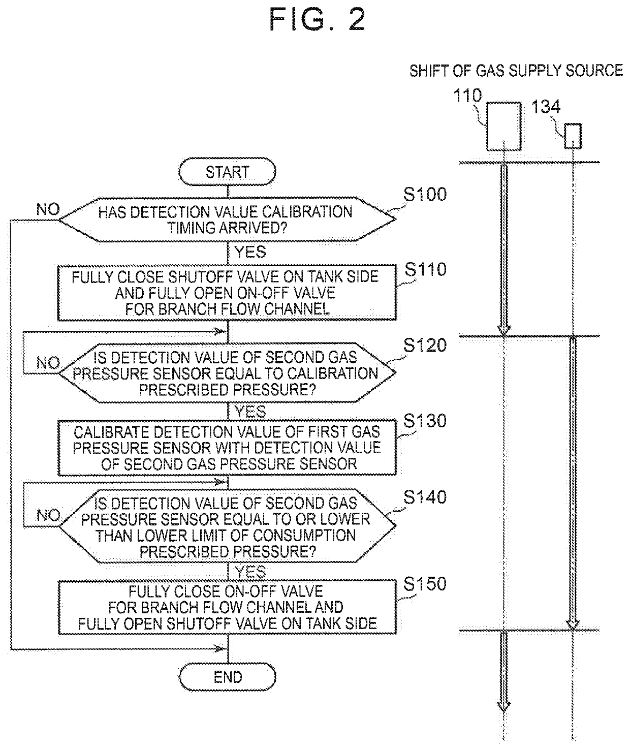
a technology of gas supply system and gas supply valve, which is applied in the direction of reactant parameter control, fuel cell operation sluggish, and gas pressure in the flow channel downstream of the shutoff valve in its closed state also falls sluggishly, so as to shorten the time to timing, the effect of subsequent calibration control and faster completion of subsequent calibration control

Active Publication Date: 2022-02-15
TOYOTA JIDOSHA KK
View PDF6 Cites 1 Cited by
  • Summary
  • Abstract
  • Description
  • Claims
  • Application Information

AI Technical Summary

Benefits of technology

[0007]In performing calibration control for calibrating the gas pressure detection value of the first gas pressure sensor through the use of the gas pressure detection value of the second gas pressure sensor, the gas supply system according to this mode of the present disclosure introduces the fuel gas in the gas supply flow channel (hereinafter referred to as the gas in the flow channel) downstream of the shutoff valve in its closed state to the buffer tank in the branch flow channel that branches off from the gas supply flow channel, instead of introducing the gas in the flow channel to the gas consuming component. This buffer tank is not in a situation where the pressure thereof is higher than the consumption prescribed gas pressure at the time of consumption of fuel gas by the gas consuming component. Thus, the gas in the flow channel is swiftly delivered to the buffer tank, and as a result, the gas pressure detection value of the second gas pressure sensor also falls swiftly. As a result, the gas supply system according to this mode of the present disclosure makes it possible to swiftly complete calibration control of the first gas pressure sensor through the use of the gas pressure detection value of the second gas pressure sensor, through the shortening of the time to the timing when the gas pressure detection value of the second gas pressure sensor reaches the prescribed gas pressure.
[0008]In the gas supply system according to the aforementioned mode of the present disclosure, the control unit may be configured to perform the calibration control while the gas supply component is in operation and hence consumes the fuel gas, and the control unit may be configured to keep the shutoff valve closed and keep the on-off valve open, until a pressure of gas supplied to the gas consuming component becomes equal to a lower-limit gas pressure as the consumption prescribed gas pressure, after completion of the calibration control. In this manner, the fuel gas in the buffer tank can be consumed by the gas consuming component, before the detection value of the second gas pressure sensor reaches the lower-limit gas pressure as the consumption prescribed gas pressure. Therefore, the buffer tank can be rendered in a state where the internal pressure thereof is low. As a result, in subsequent calibration control of the first gas pressure sensor, the gas in the flow channel is delivered to the buffer tank within a shorter time. Thus, subsequent calibration control can be more swiftly completed.
[0009]In the gas supply system according to the aforementioned mode of the present disclosure, the control unit may be configured to perform the calibration control while the gas supply component is out of operation and hence does not consume the feel gas, and the control unit may be configured to keep the shutoff valve closed and keep the on-off valve open and cause the gas consuming component to consume the fuel gas in the buffer tank, when the gas consuming component starts operating after completion of the calibration control. In this manner, when the gas consuming component starts operating after calibration control of the first gas pressure sensor, the fuel gas delivered to the buffer tank during calibration control of the first gas pressure sensor can be delivered to the gas consuming component to be consumed. As a result, a fall in the internal pressure of the buffer tank and swift delivery of the gas in the flow channel to the buffer tank at the time of subsequent calibration control of the first gas pressure sensor are made possible, through the consumption of the fuel gas delivered to the buffer tank prior to the start of operation with the consumption of gas in the gas consuming component, by the gas consuming component. Thus, subsequent calibration control can be more swiftly completed. Besides, fuel economy can also be improved through the consumption of the fuel gas in the buffer tank resulting from the start of operation of the gas consuming component after calibration control of the first gas pressure sensor.
[0011]In the gas supply system according to the aforementioned mode of the present disclosure, the gas consuming component may be a fuel cell. In this manner, the necessity to operate the fuel cell is eliminated even if calibration control of the first gas pressure sensor is performed when the operation of the fuel cell is stopped, by refraining from delivering fuel gas to the fuel cell during the period of calibration control of the first gas pressure sensor, in addition to the already-mentioned effects such as the shortening of calibration control of the first gas pressure sensor and the like. As a result, the noise resulting from the operation of the fuel cell can be erased or suppressed.

Problems solved by technology

On the other hand, under the situation where electric power generation is stopped, no electric power or only a minute quantity of electric power is fed from the fuel cell, so the fuel cell operates sluggishly.
In consequence, the pressure of the hydrogen gas in the flow channel downstream of the shutoff valve in its closed state also falls sluggishly, and the fall in the sensor detection value does not progress correspondingly.
Besides, there is an apprehension that the operation duration time of the fuel cell may become long, and that the operation sound resulting from the operation of the fuel cell may become noise.

Method used


Image

  • Gas supply system
  • Gas supply system
  • Gas supply system

Examples


first embodiment

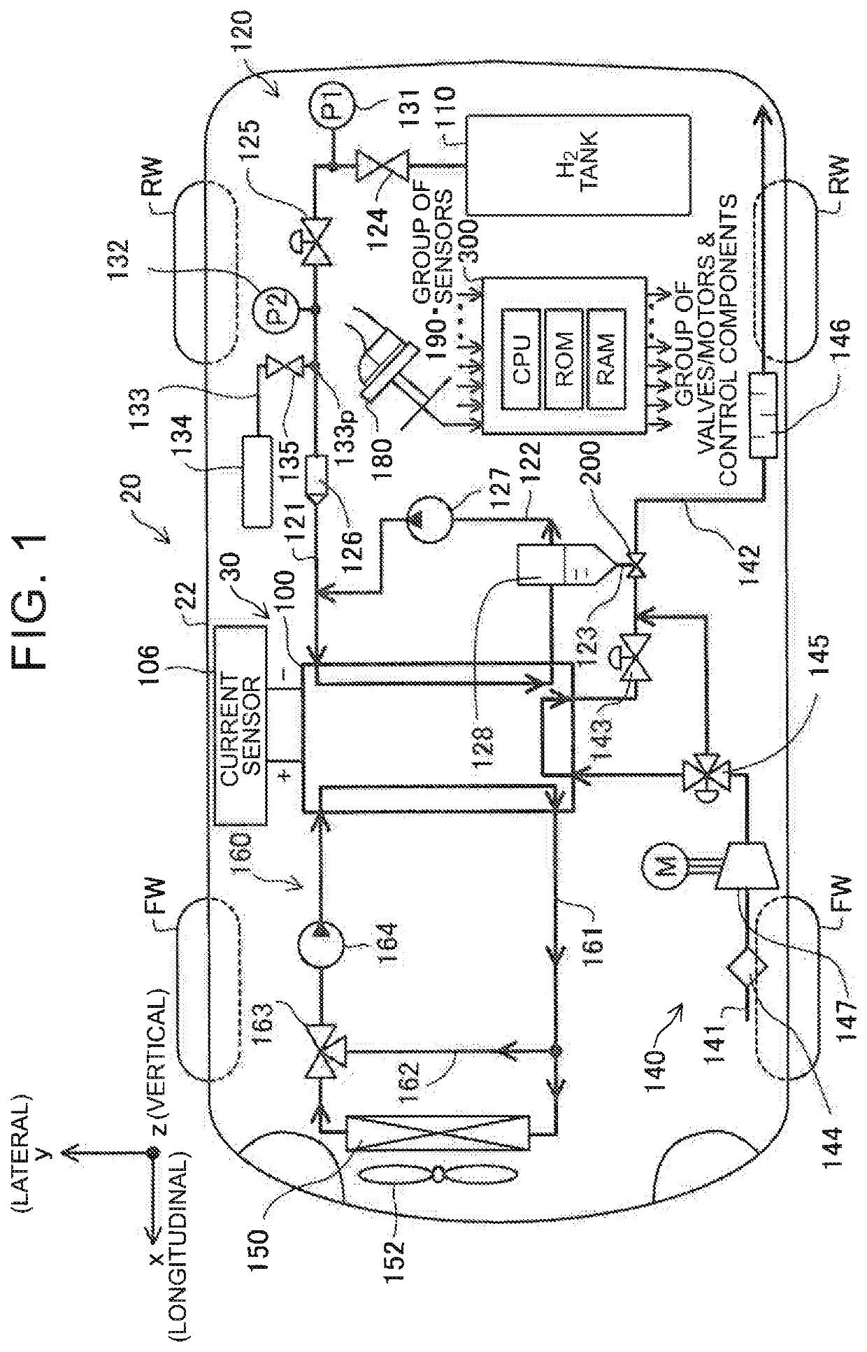
[0017]FIG. 1 is an illustrative plan view schematically showing a vehicle 20 that is mounted with a fuel cell system 30. The vehicle 20 has a vehicle body 22 that is mounted with the fuel cell system 30. The fuel cell system 30 includes a fuel cell 100, a hydrogen gas supply system 120 including a hydrogen gas tank 110 as a gas supply system according to the present disclosure, an air supply system 140 including a motor-driven compressor 147, a cooling system 160 including a radiator 150 and a fan 152, a group of sensors 190, and a control unit 300. The fuel cell system 30 supplies an electric power generated by the fuel cell 100 or an electric power with which a secondary battery (not shown) is charged, to loads including a motor (not shown) for driving front wheels. Incidentally, the fuel cell 100 is an exemplary gas consuming component in the present application.

[0018]The fuel cell 100 has a stack structure that is constituted by stacking battery cell units (not shown) as electri...

second embodiment

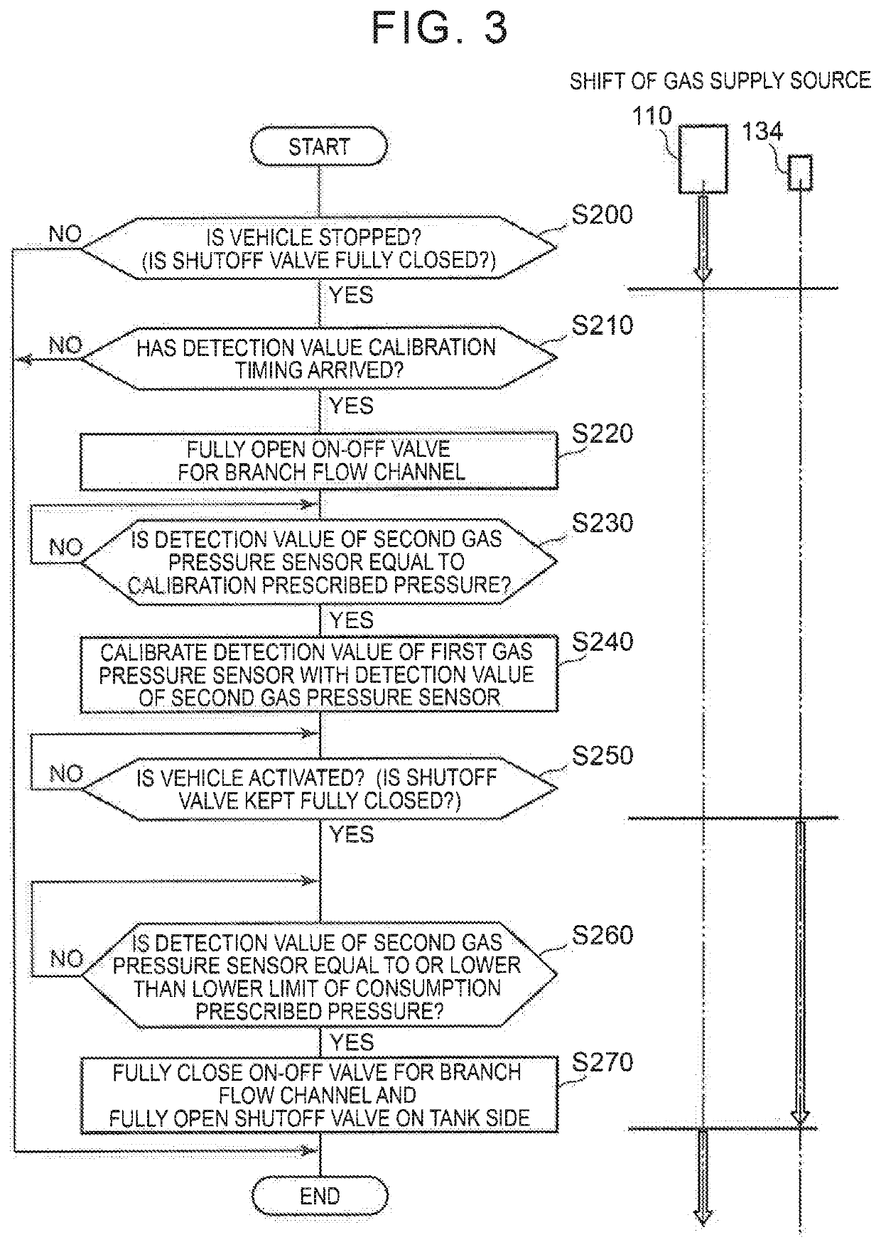
[0039]FIG. 3 is a flowchart representing the processing contents of calibration control according to the present disclosure for calibrating the detection value of the first gas pressure sensor 131 with the wide pressure detection range. Incidentally, in FIG. 3 as well, the shift of the supply source of the hydrogen gas supplied to the fuel cell 100 is shown in conjunction with the shift of the processing of calibration control.

[0040]In calibration control of the first gas pressure sensor 131 according to this second embodiment of the present disclosure, the control unit 300 first determines whether or not the vehicle 20 is stopped (step S200). If the vehicle 20 is not stopped, the control unit 300 ends the present routine. When this vehicle 20 is stopped, an ignition switch is off. Therefore, the vehicle 20 is stopped during a non-operation period in which the fuel cell 100 does not consume hydrogen gas with no hydrogen gas delivered to the fuel cell 100 by the hydrogen gas supply c...


PUM

PropertyMeasurementUnit
gas pressureaaaaaaaaaa
pressureaaaaaaaaaa
pressureaaaaaaaaaa

Abstract

A shutoff valve, a first gas pressure sensor, a pressure reducing valve, a second gas pressure sensor, and a gas supply component are provided, sequentially from a gas tank side, in a gas supply flow channel that extends from the gas tank to a gas consuming component. Besides, a buffer tank is provided, via an on-off valve, in a branch flow channel that branches off from the gas supply flow channel between the pressure reducing valve and the gas supply component. This buffer tank is in a situation where the pressure of the buffer tank is not higher than a consumption prescribed gas pressure. In calibrating the first gas pressure sensor, with the shutoff valve closed and with the on-off valve open, a detection value of the first gas pressure sensor is calibrated through the use of a detection value of the second gas pressure sensor.

Description

INCORPORATION BY REFERENCE[0001]The disclosure of Japanese Patent Application No. 2017-022658 filed on Feb. 10, 2017 including the specification, drawings and abstract is incorporated herein by reference in its entirety.BACKGROUND1. Technical Field[0002]The present disclosure relates to a gas supply system.2. Description of Related Art[0003]A gas supply system stores fuel gas of a gas consuming component, for example, hydrogen gas as fuel gas of a fuel cell into a gas tank at a high pressure, and supplies the stored hydrogen gas to an anode of the fuel cell. Then, with a view to calibrating a sensor detection value required for the detection of an amount of the gas remaining in the gas tank, there is proposed a method of calibrating a detection value of a high-pressure sensor that is provided upstream of a pressure reducing valve in a gas supply flow channel, with a detection value of a low-pressure sensor that is provided downstream of the pressure reducing valve (e.g., Japanese Pa...

Claims


Application Information

Patent Timeline
Patent Type & Authority Patents(United States)
IPC IPC(8): H01M8/04089H01M8/04082H01M8/04223H01M8/04746H01M8/0438
CPCH01M8/04104H01M8/04201H01M8/04231H01M8/04388H01M8/04753Y02E60/50
Inventor FUJITA, KEISUKE
Owner TOYOTA JIDOSHA KK
Why Eureka
Try Eureka