Current transformer, protection device and electrical circuit breaker including such a transformer

a protection device and transformer technology, applied in the direction of transformer/inductance magnetic cores, transformers/inductances, continuously variable inductances/transformers, etc., can solve the problems of components and heat generation of magnetic circuits, and achieve the effect of avoiding or reducing the temperature increase of the magnetic circui

Active Publication Date: 2022-04-05
SCHNEIDER ELECTRIC IND SAS
View PDF9 Cites 1 Cited by
  • Summary
  • Abstract
  • Description
  • Claims
  • Application Information

AI Technical Summary

Benefits of technology

[0008]The aim of the invention is a current transformer capable of avoiding or reducing temperature increases in the magnetic circuit, as well as a protection device and a circuit breaker comprising such a current transformer.
[0018]Preferably, the material of the static device comprises cutouts for avoiding current losses through eddy currents.

Problems solved by technology

These iron losses result in heating of the magnetic circuit, as well as of the components adjoining or in contact with the magnetic circuit.

Method used


Image

  • Current transformer, protection device and electrical circuit breaker including such a transformer
  • Current transformer, protection device and electrical circuit breaker including such a transformer
  • Current transformer, protection device and electrical circuit breaker including such a transformer

Examples


first embodiment

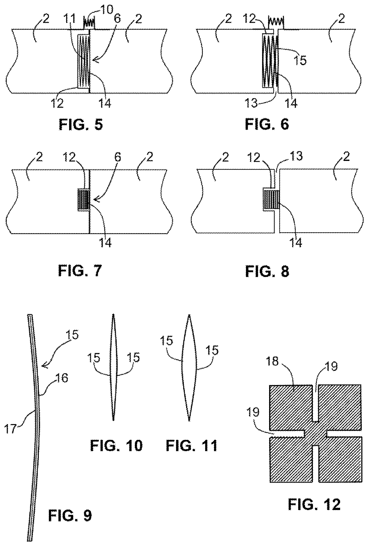
[0038]According to the device for limiting magnetic flux according to the temperature that is shown in FIGS. 5 to 8, the device 6 for varying magnetization comprises a mechanical device 11 housed in a recess 12 of the magnetic circuit 2 in order to produce a gap 13 or to increase a gap by opening the magnetic circuit 2 when the temperature reaches said predetermined threshold. Preferably, said predetermined threshold is between 120° C. and 180° C.

[0039]The mechanical device 11 creates an additional gap, which will increase from a threshold temperature. To this end, the mechanical device 11 comprises strips 14 of bi-metal, which are mounted head-to-tail and are housed in the recess 12 in order to effect a separation of the magnetic circuit, thus generating a gap 13. The recess 12 allows the bi-strips to be retained in position so as to produce a thrust perpendicular to the deformation thereof under the effect of the temperature. A retention device 10 of the magnetic circuit comprises...

second embodiment

[0048]FIGS. 14 and 15 show arrangements according to a device 18 for varying static magnetization for limiting the magnetic flux according to the temperature. The magnetic circuit comprises notches or openings for creating gaps at high temperatures. In FIG. 14, the gap will be complete since an opening 22 occupies the entire section. In this case, a retention device 10 prevents any movement of the magnetic circuit. In FIG. 15, the gap is partial with a notch 23 only occupying a portion of the section of the magnetic circuit. Thus, an element 18 made of magnetic material with a low Curie point (Tc) is inserted into the notches or openings 22 or 23. Preferably, the distance of the gap of the openings 22 or 23 is between 0.5 and 1 mm.

[0049]FIG. 16 shows a block diagram of a circuit breaker 30 and a protection device 31 comprising a transformer 1 according to one embodiment of the invention.

[0050]The electronic protection device 31 comprises an electronic processing unit 32 connected to...


PUM

PropertyMeasurementUnit
temperatureaaaaaaaaaa

Abstract

The current transformer includes a magnetic circuit made of magnetic material that is intended to be placed around a primary conductor, and a secondary winding that is wound onto a portion of the magnetic circuit in order to deliver a secondary current to processing circuits. In this current transformer the magnetic circuit includes at least one device for varying the magnetization of a portion of the magnetic circuit according to the temperature in order to limit or to decrease the magnetic flux in the magnetic circuit when the temperature of the magnetic circuit increases. The protection device and the electrical circuit breaker include such a transformer.

Description

TECHNICAL FIELD[0001]The invention relates to a current transformer comprising:[0002]a magnetic circuit made of magnetic material that is intended to be placed around a primary conductor; and[0003]a secondary winding that is wound onto a portion of said magnetic circuit in order to deliver a secondary current to a processing circuit.[0004]The invention also relates to a protection device and a circuit breaker comprising such a current transformer.PRIOR ART[0005]A known current transformer 1 is shown in FIG. 1. It comprises a magnetic circuit 2 that is intended to be placed around a primary conductor 3, and a secondary winding 4 that is wound onto a portion 5 of said magnetic circuit. The magnetic circuit is often produced as stacked sheets. These sheets are predominantly made up of iron and are designed to operate at the frequencies of the electricity grid, in particular at 50 Hz or 60 Hz.[0006]When the fundamental frequency of the electricity grid increases and exceeds 100 Hz or wh...

Claims


Application Information

Patent Timeline
Patent Type & Authority Patents(United States)
IPC IPC(8): H01F27/00H01F27/24H01H71/74H02H1/00H01F38/28
CPCH01F27/008H01F27/24H01F38/28H01H71/7463H02H1/0007H01F38/30H01F38/32H01F27/245H01F3/14H01F21/06H01F29/10H01F38/023H01F2003/106H01F2027/406H01F2038/305
Inventor MAS, PATRICKSHI, XIAODONG
Owner SCHNEIDER ELECTRIC IND SAS
Why Eureka
Try Eureka