
Oil separating device

Active Publication Date: 2022-04-19
BRUSS SEALING SYST
View PDF17 Cites 0 Cited by
  • Summary
  • Abstract
  • Description
  • Claims
  • Application Information

AI Technical Summary

Benefits of technology

The invention is a simple oil separating device that is small and efficient in separating oil from air. It optimizes the use of existing negative pressure levels, resulting in improved utilization.

Problems solved by technology

Furthermore, the design is a compromise of the available space.
However, electrically driven plate separators are complex and therefore costly.

Method used


Image

  • Oil separating device
  • Oil separating device
  • Oil separating device

Examples


embodiments

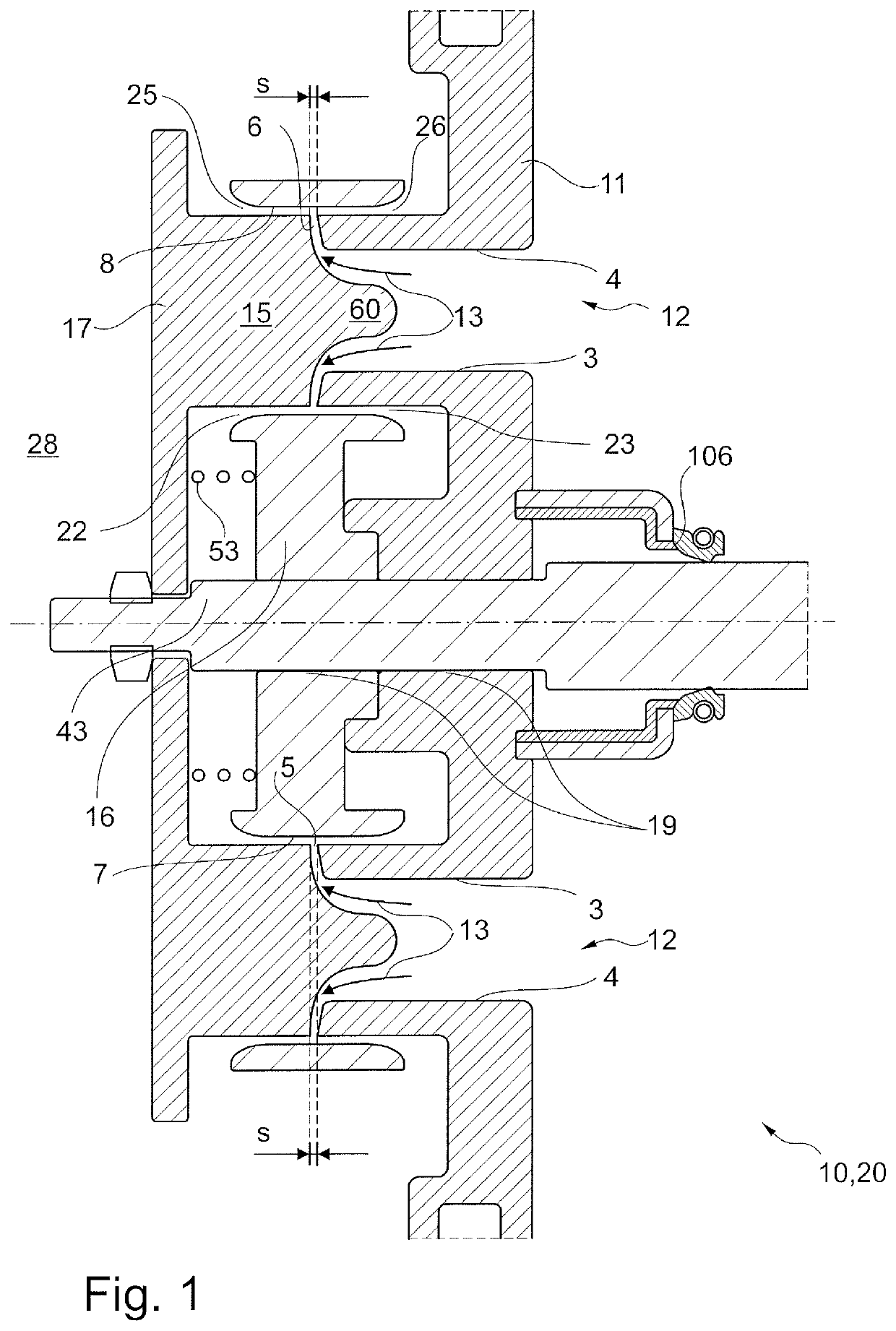
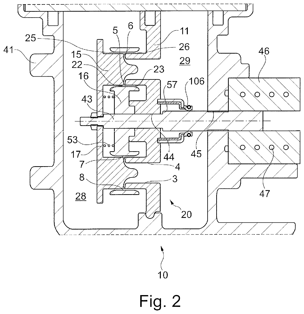
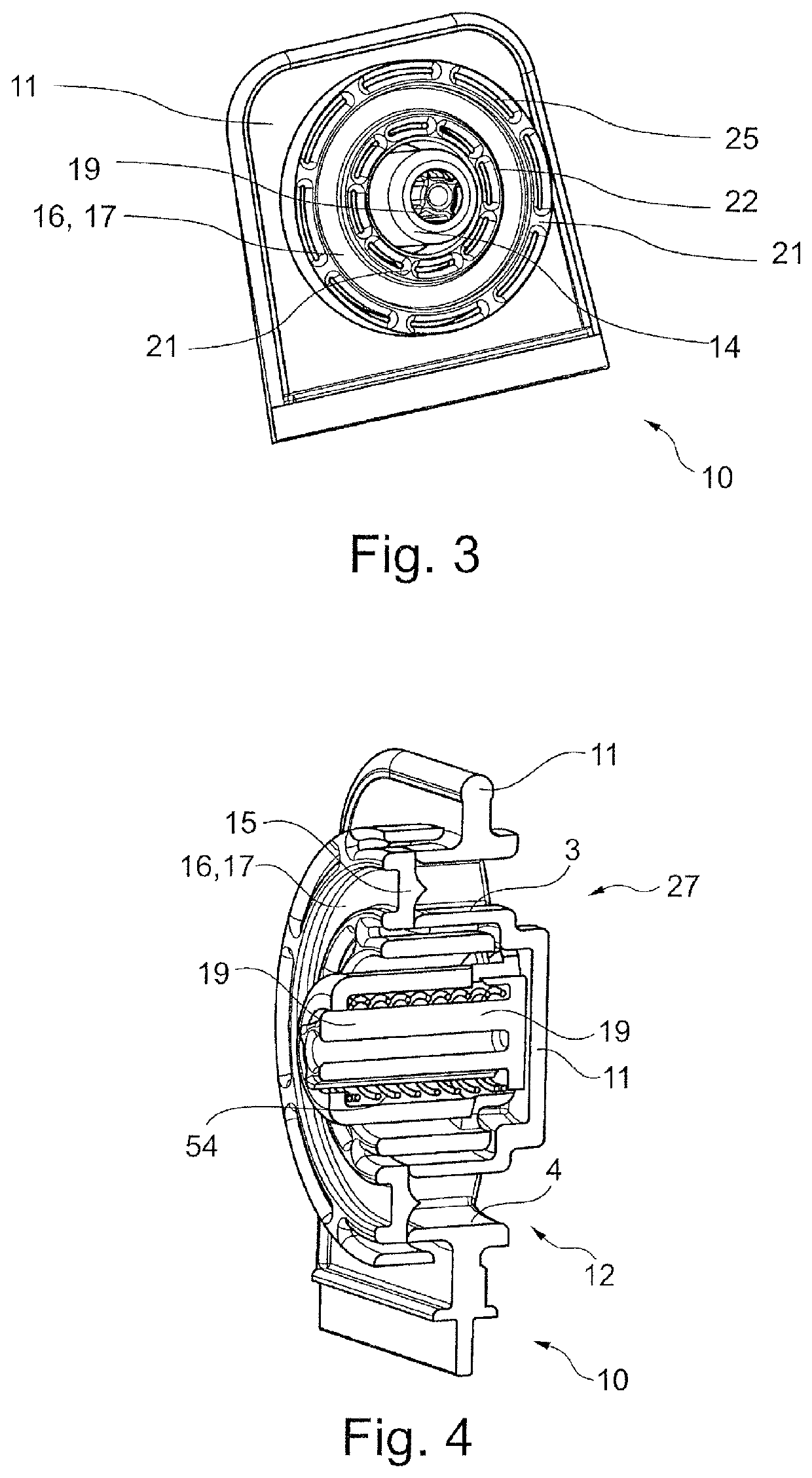
[0111]Embodiment 1. Oil separating device (10) for crankcase ventilation of an internal combustion engine, comprising an oil separator (20) having a gas inlet line (12), which has an outlet end, and a gap-defining element (15), characterised in that the gas inlet line (12) for flowing blow-by gas (13) has an inner wall (3) and an outer wall (4), wherein an inner annular gap (5) is formed or can be formed between the gap-defining element (15) and the outlet end on the inner wall (3) of the gas inlet line (12) and an outer annular gap (6) is formed or can be formed between the gap-defining element (15) and the outlet end of the outer wall (4) of the gas inlet line (12), wherein, in the flow direction, an inner baffle (7) is arranged behind the inner annular gap (5) and an outer baffle (8) is arranged behind the outer annular gap.

[0112]Embodiment 2. Oil separating device (10) according to embodiment 1, characterised in that the inner annular gap (5) and the outer annular gap (6) are ar...


PUM


Abstract

The present invention relates to an oil separating device for crankcase ventilation of an internal combustion engine, comprising an oil separator having a gas inlet line, which has an outlet end, and a gap-defining element, wherein the gas inlet line for flowing blow-by gas has an inner wall and an outer wall, wherein an inner annular gap is formed or can be formed between the gap-defining element and the outlet end on the inner wall of the gas inlet line and an outer annular gap is formed or can be formed between the gap-defining element and the outlet end of the outer wall of the gas inlet line, wherein, in the flow direction, an inner baffle is arranged behind the inner annular gap and an outer baffle is arranged behind the outer annular gap.

Description

CROSS-REFERENCE TO A RELATED APPLICATION[0001]This application claims priority under 35 U.S.C. § 119(e) of German Patent Application No. DE 10 2019 217 901.0, filed on Nov. 20, 2019, which is incorporated herein by reference in its entirety.FIELD OF THE INVENTION[0002]The present invention relates to an oil separating device for crankcase ventilation of an internal combustion engine, comprising an oil separator having a gas inlet line, which has an outlet end, and a gap-defining element. The invention also relates to a corresponding system for crankcase ventilation of an internal combustion engine.BACKGROUND OF THE INVENTION[0003]DE 100 51 307 B4, EP 1 285 152 B1 and WO 2016 / 015976 A1, for example, disclose oil separating devices having a rigid plate that is displaceable against the force of a spring.[0004]EP 3 192 987 A1 discloses an oil separating device of the type mentioned at the outset. The gap between the gap-defining element and the inlet pipe is set on the basis of the prel...

Claims


Application Information

Patent Timeline
IPC IPC(8): F01M13/04
CPCF01M13/0416F01M2013/0433F01M13/04F01M13/00F16N31/02
Inventor HINZ, TORGEKNAUS, ARTURRUST, STEPHANBRAND, MANFRED
Owner BRUSS SEALING SYST
Learn More