Methods and apparatuses for temperature measurement

a technology of temperature measurement and apparatus, applied in the field of methods and apparatuses for temperature measurement, can solve the problems of inability to safely and accurately penetrate and measure the product, inability to reliably detect the temperature of the product, and inability to accurately measure the product, so as to avoid spikes or spurious readings, accurate and repeatable temperature profiles

Active Publication Date: 2022-04-26
CAIRNS INTPROP
View PDF20 Cites 1 Cited by
  • Summary
  • Abstract
  • Description
  • Claims
  • Application Information

AI Technical Summary

Benefits of technology

[0020]In certain embodiments there are a plurality of said plates which are joined to form a continuous loop and form part of the conveyance system. This enables the second members to form part of the conveyance system and removes the requirement for the object to be moved onto a separate support for the measurement to take place. The plates can be pivoted relative to each other to permit the forming of the loop. The pivots may be about an axis substantially perpendicular to the direction of travel but in the same plane as the direction of conveyance to form a caterpillar-type track combination which rotates around driven rollers in a substantially vertical loop. Alternatively the pivots may be about an axis substantially perpendicular to the plane of the conveyance of the objects to form a scale-type track which rotates in a substantially horizontal loop.
[0099]The method may further include the step of guiding the object to arrive at the measurement position in a particular orientation, or with a particular degree of precision. This can ensure accurate positioning of the probe within the object.

Problems solved by technology

The temperature measured by probing therefore also only applies to a small volume of material around the probe, and the probing is subject to significant operator-dependent variability.
In the case of frozen products it is very difficult, and in some cases not possible, to safely and accurately penetrate and measure the product.
However, the results from such sensors are not particularly reliable as they require the sensor to be pointed at a clean and non-shiny area.
Microwave radiometric temperature measurements are inherently non-invasive and non-destructive.
The present inventors have attempted such an implementation and discovered that there are numerous problems, such that simply implementing the apparatus described in that document in a production line is not possible.
Without limitation, these problems include the ability to form a completely sealed cavity in a production line setting to ensure coupling of the radiation from the sample to the radiometer.
As the radiation levels being measured and on which the temperature calculation is performed are very small, typically in the range of picowatts (10−12 W), even minor imperfections in the sealing of the cavity can significantly affect the accuracy of the resultant temperature readings.

Method used


Image

  • Methods and apparatuses for temperature measurement
  • Methods and apparatuses for temperature measurement
  • Methods and apparatuses for temperature measurement

Examples


first embodiment

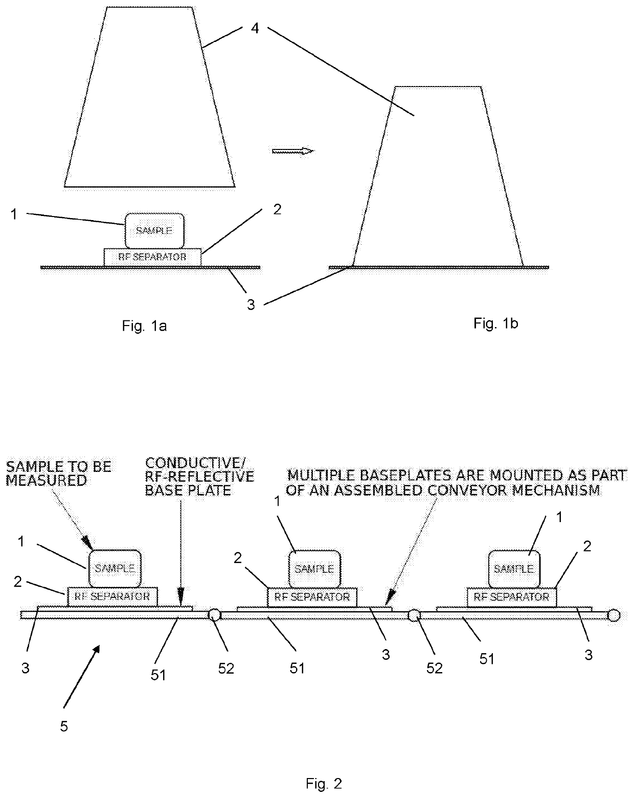
[0152]FIG. 2 shows the present invention in which a plurality of separate base plates 3 are mounted as part of a conveyor mechanism 5. Each base plate 3 has a separator 2 mounted on it in a substantially central position. Samples 1 can be placed onto or guided to sit on each separator as part of a larger industrial process.

[0153]The conveyor mechanism includes a plurality of rigid plate elements 51, each of which has a base plate 3 and separator 2. Each plate element 51 is connected to the adjacent plate element by a hinged connector 52. The connectors 52 can allow the conveyor mechanism as a whole to form a closed loop, for example as shown conceptually in FIG. 3. In alternative arrangements, the plate elements 51 may be connected so as to allow connection in a closed loop in the plane of the plate elements (i.e. permitting rotation of the plate elements relative to the adjacent plate elements about an axis perpendicular to the plane of the plate elements).

second embodiment

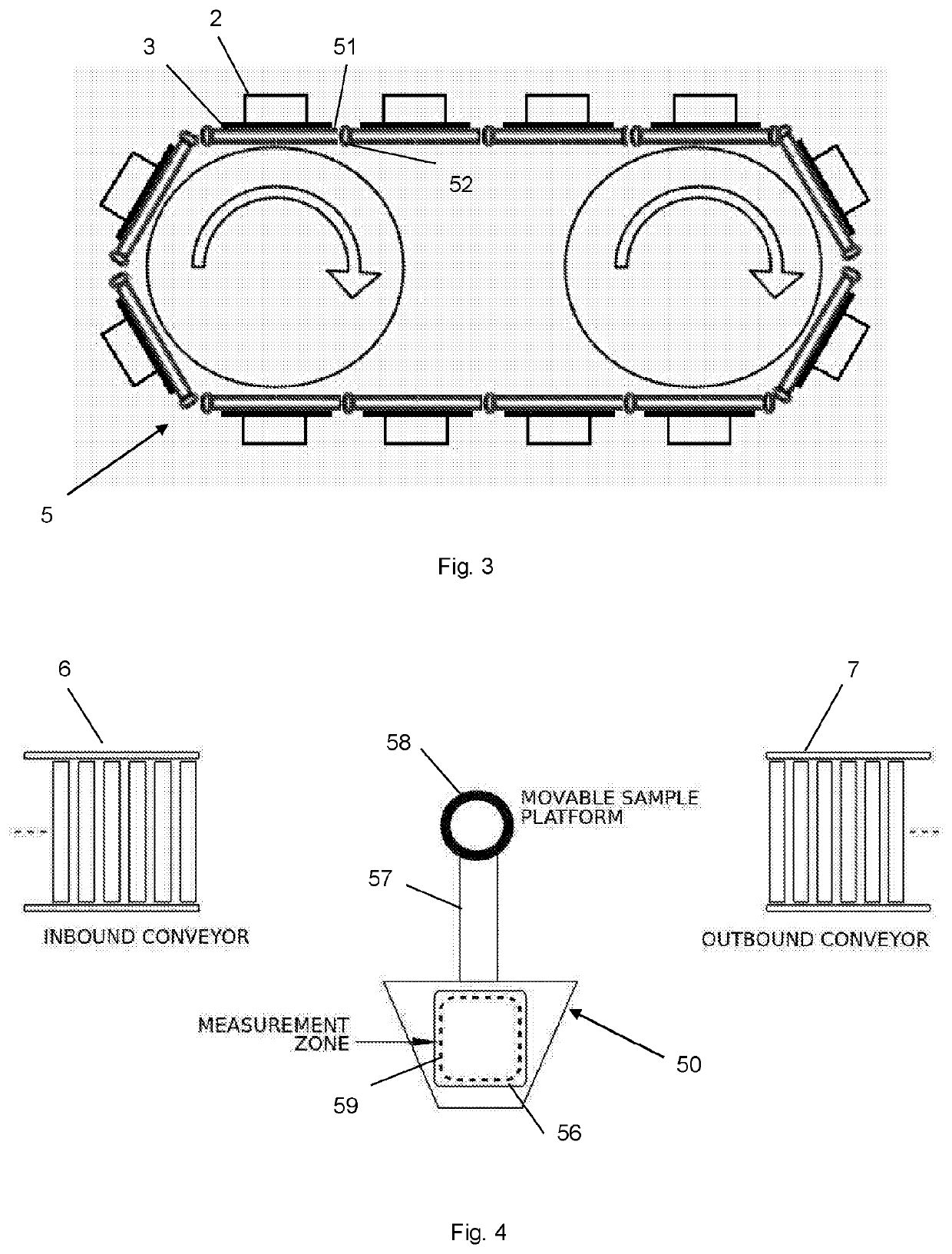
[0154]FIG. 4 shows, conceptually, the present invention in which a movable sample platform 50, which has an arm 57 connected to a paddle 56 and is rotatable about a substantially vertical axis (perpendicular to the plane of the figure) passing through a hub 58. The paddle 56 has a measurement zone 59 located on it. The sample platform 50 moves around the hub 58 so as to move samples between an inbound conveyor 6 and an outbound conveyor 7 via a measurement point at which the sample can be measured.

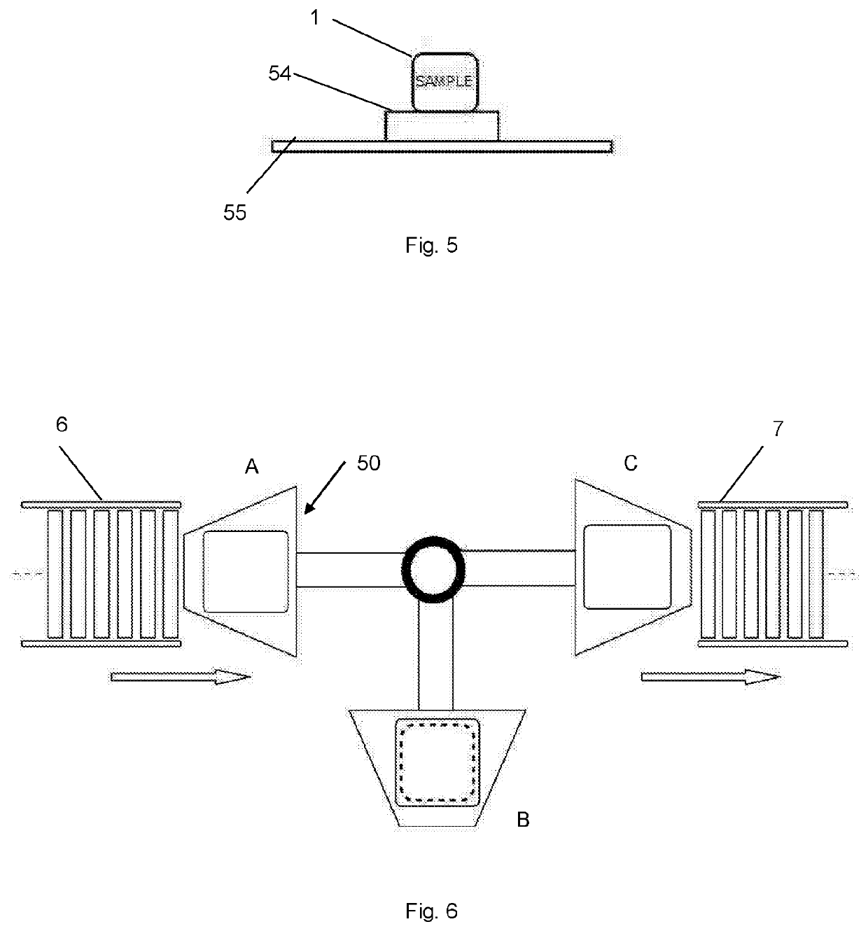
[0155]FIG. 5 shows a side view of the sample platform 60, which has a base plate 55 which is conductive / radiofrequency-reflective and a separator 54 which is transparent or substantially transparent to radiofrequency radiation and on which the sample 1 is placed in a similar configuration to the base plates 3 and separators 2 described in relation to the first embodiment above. In an alternative configuration, only the measurement zone 59 need be conductive and the surrounding parts of the...


PUM

PropertyMeasurementUnit
temperaturesaaaaaaaaaa
temperatureaaaaaaaaaa
depthaaaaaaaaaa

Abstract

This invention relates to a method and apparatus for automated measurement of the temperatures of samples on a production line without any human intervention. In one aspect the apparatus has a conveyance system; and a temperature measurement unit having: a first member and a second member which are movable relative to each other between at least a first position in which the first and second members cooperate to form an internal space which is substantially internally reflective of radiofrequency radiation and a second position in which the object can be introduced into said internal space; and a radiometer arranged so that it is coupled to said internal space, wherein the conveyance system is arranged to convey the object to a measurement position in said internal space whilst the first and second members are in the second position, for a measurement of the radiation emitted from the object to be performed by the radiometer when the first and second members are in the first position and to convey the object away from said measurement position once the measurement has been performed and said first and second members have returned to the second position. The apparatus allows for recording and storing of measured temperature information. Embodiments of the invention provide for auto-calibration of the apparatus and automated testing and rejection of samples which do not meet pre-defined criteria.

Description

FIELD OF THE INVENTION[0001]The present invention relates to methods and apparatuses for temperature measurement. It is particularly, but not exclusively, related to methods and apparatuses which measure the temperature of products in a production line setting.BACKGROUND OF THE INVENTION[0002]Food production companies constantly need to improve productivity and reduce waste and labour / staff. They also need to take care to monitor temperatures throughout their production processes and at critical control points (“CCP”). This includes the temperatures of packaged foods that need be measured before storage or despatch.[0003]At present, the most common technique is invasive probing by thermocouple, thermistor, or resistive temperature detectors (RTDs). These methods require a skilled operator with a probe that can pierce or break into / through the packaging. It is then necessary to wait for the probe to stabilise with the core temperature of the product, which can take typically from thr...

Claims


Application Information

Patent Timeline
Patent Type & Authority Patents(United States)
IPC IPC(8): G01K13/06B65G47/71G01K1/14G01K1/024G01K11/00G01K15/00
CPCG01K13/06B65G47/71G01K1/024G01K1/146G01K11/006G01K15/005G01K2207/04G01K2207/06
Inventor CAIRNS, ROBINHOLT, MICHAEL JAMES
Owner CAIRNS INTPROP
Why Eureka
Try Eureka