
Imprint apparatus, imprint method, and method for manufacturing article

a technology which is applied in the field of imprinting apparatus and imprinting method for manufacturing articles, can solve the problems of high economic costs of operating the imprinting apparatus, unfilled defects (pattern defects) in some cases, and the effect of high economic cos

Active Publication Date: 2022-04-26
CANON KK
View PDF4 Cites 0 Cited by
  • Summary
  • Abstract
  • Description
  • Claims
  • Application Information

AI Technical Summary

Benefits of technology

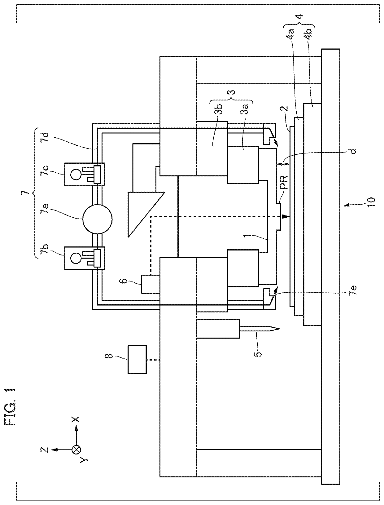
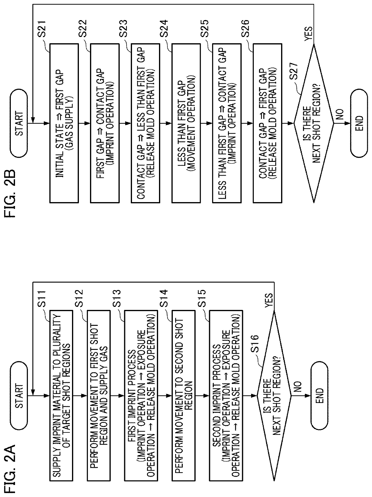
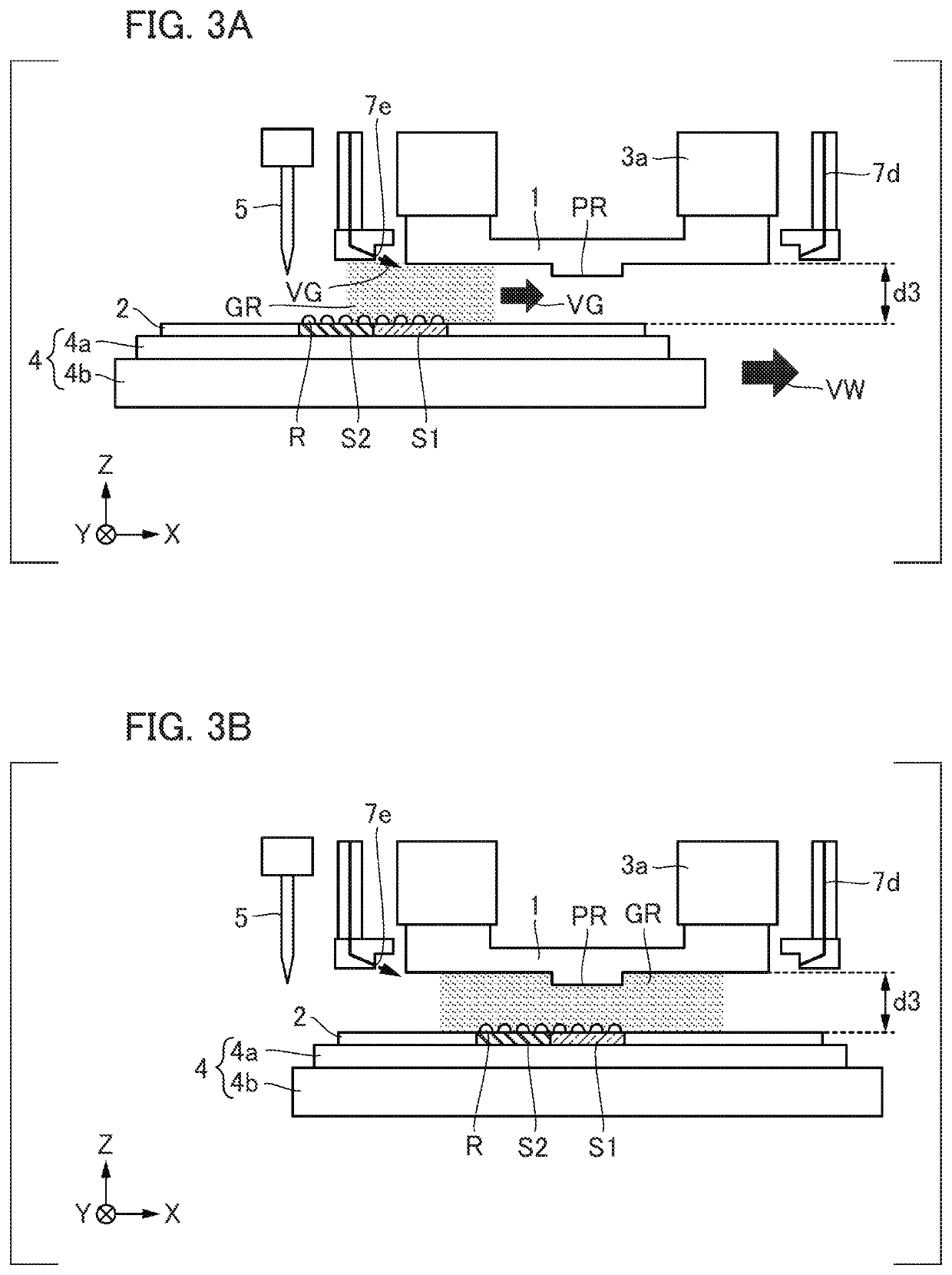
[0007]The present invention is an imprint apparatus for bringing a mold into contact with an imprint material supplied onto a plurality of shot regions formed on a substrate and forming a pattern on the substrate including: a gas supply unit configured to supply a gas to a space between the mold and the substrate; a positioning unit configured to change a gap between the mold and the substrate; and a controller configured to control the gas supply unit and the positioning unit, wherein the controller causes second contact between a second shot region different from a first shot region and the mold after first contact between the first shot region having the imprint material supplied thereon among the plurality of shot regions and the mold and controls the positioning unit so that a second gap of the mold and the substrate at the time of changing a relative position between the mold and the substrate in a surface direction from the first shot region to the second shot region is shorter than a first gap of the mold and the substrate at the time of gas supply.

Problems solved by technology

At the time of imprinting, air (a residual gas) between the mold and the imprinting material may mix into an uncured imprint material as air bubbles, resulting in unfilled defects (pattern defects) in some cases.
In such an imprint apparatus, when an amount of consumption of replacement gas is large, there is a problem that the economic costs of operating the imprint apparatus are high.

Method used


Image

  • Imprint apparatus, imprint method, and method for manufacturing article
  • Imprint apparatus, imprint method, and method for manufacturing article
  • Imprint apparatus, imprint method, and method for manufacturing article

Examples


first embodiment

[0019]In this specification and the accompanying drawings, directions are illustrated in an XYZ coordinate system in which a plane with a direction parallel to a surface of a substrate is set to an XY plane. Directions parallel to an X axis, a Y axis, and a Z axis in the XYZ coordinate system are set to an X direction, a Y direction, and a Z direction and rotation around the X axis, rotation around the Y axis, and rotation around the Z axis are set to θX, θY, and θZ. Control or driving with respect to the X axis, the Y axis, and the Z axis refers to control or driving in a direction parallel to the X axis, a direction parallel to the Y axis, and a direction parallel to the Z axis. Positioning refers to controlling a position, an attitude, or an inclination. Alignment can include controlling a position, an attitude, and an inclination of at least one of a substrate and a mold.

[0020]FIG. 1 is a schematic diagram illustrating a constitution of an imprint apparatus 10 according to a fir...

second embodiment

[0079]An imprint apparatus 10 according to a second embodiment of the present invention will be described below. The matters which are not mentioned in the second embodiment are the same as the first embodiment. In the second embodiment, the controller 8 supplies a gas again if a predetermined condition is satisfied, such as if a distance d exceeds a set threshold value due to some causes during a mold release operation.

[0080]FIG. 13 is a flowchart for describing an imprint process of an imprint apparatus 10 according to the second embodiment. Steps S11 to S13 in FIG. 13 are the same as those in the first embodiment and description thereof will be omitted.

[0081]In Step S31, after completion of the release mold operation, the distance d is compared with a predetermined threshold value. The predetermined threshold value is equivalent to, for example, the maximum value d2 of the second gap in the first embodiment, which can be preset by the calculation method described in the first emb...


PUM

PropertyMeasurementUnit
wavelengthsaaaaaaaaaa
distanceaaaaaaaaaa

Abstract

Provided is an apparatus which is advantageous in view of reduction of consumption of a replacement gas. An apparatus for forming a pattern on a substrate using a mold includes a gas supply unit, a positioning unit and a controller. The controller controls a gas supply unit and a positioning unit and, causes second contact between a second shot region different from a first shot region and the mold after first contact between a first shot region having a material supplied thereon among the plurality of shot regions and the mold and controls the positioning unit so that a second gap which is the distance at the time of changing a relative position between the mold and the substrate in a surface direction from the first shot region to the second shot region is shorter than a first gap which is the distance at the time of gas supply.

Description

BACKGROUND OF THE INVENTIONField of the Invention[0001]The present invention relates to an imprint apparatus, an imprint method, and a method for manufacturing an article.Description of the Related Art[0002]The demands for miniaturization of semiconductor apparatuses has progressed and micro-fabrication techniques are attracting attention in which an imprint material on a substrate is formed (molded) with a mold and cured to form a pattern on the substrate in addition to conventional photolithography techniques. Such techniques are referred to as imprint techniques and it is possible to form a fine pattern on the order of several nanometers on a substrate therewith.[0003]As one type of imprint technique, there is a light curing method. An imprint apparatus adopting a light curing method forms a pattern on a substrate by bringing (imprinting) a mold into contact with (on) a photocurable imprint material supplied onto the substrate, irradiating the imprint material with light to cure ...

Claims


Application Information

Patent Timeline
Patent Type & Authority Patents(United States)
IPC IPC(8): B82Y10/00G03F7/00B82Y40/00
CPCG03F7/002B82Y10/00B82Y40/00G03F7/0002G03F7/70775G03F7/70858H01L21/027H01L21/67017
Inventor MURAKAMI, YOSUKEHAMAYA, ZENICHI
Owner CANON KK
Learn More