DC circuit breaker
a circuit breaker and circuit breaker technology, applied in circuit breakers, circuit breakers for excess currents, air breakers, etc., can solve problems such as power loss, and achieve the effects of reducing the price of the dc circuit breaker, reducing the power loss, and ensuring the ability to maintain low voltag
- Summary
- Abstract
- Description
- Claims
- Application Information
AI Technical Summary
Benefits of technology
Problems solved by technology
Method used
Image
Examples
first embodiment
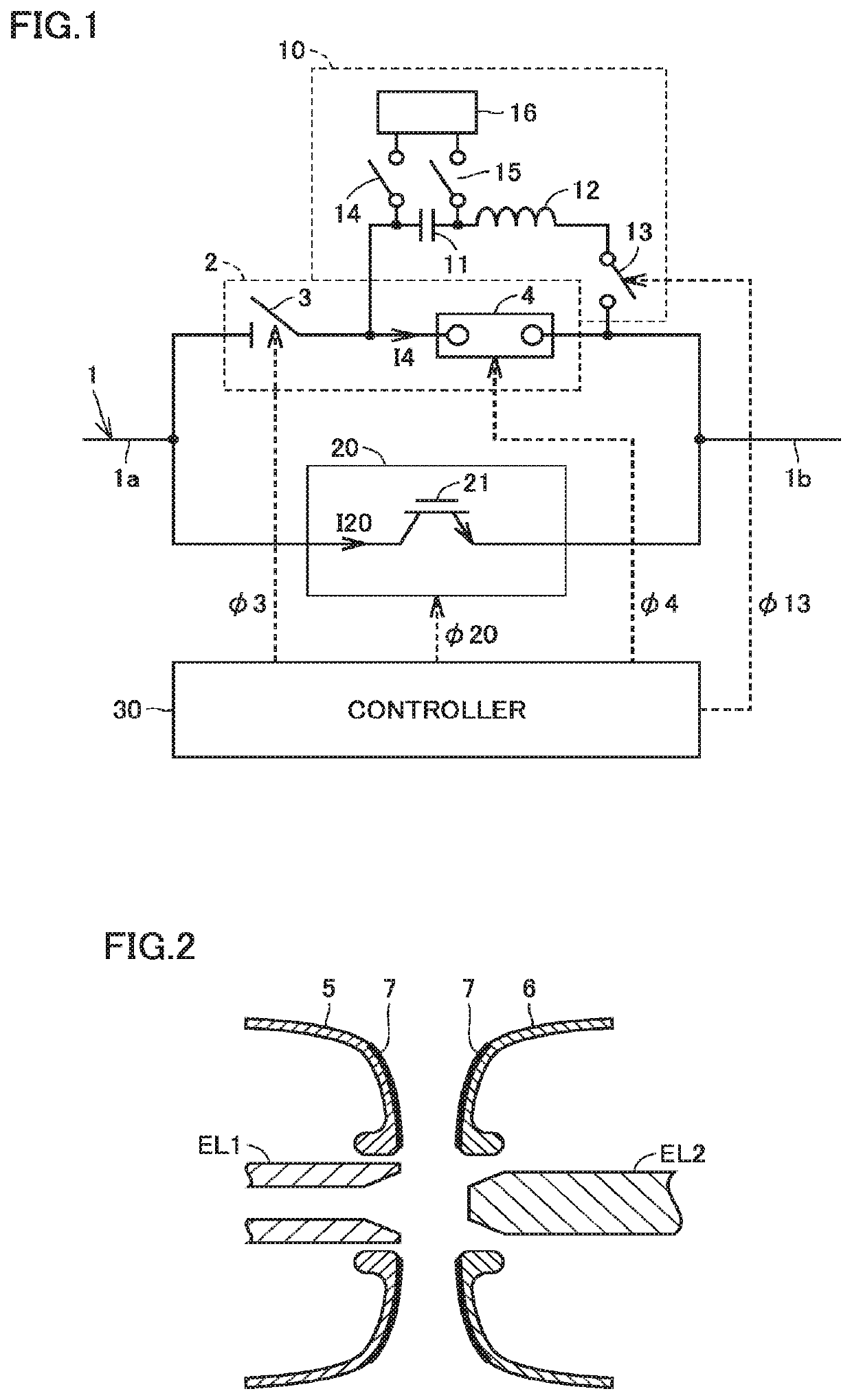
[0027]FIG. 1 is a circuit block diagram showing a configuration of a DC circuit breaker in a first embodiment of the present invention. In FIG. 1, this DC circuit breaker is provided on an electrical path 1 of a DC power transmission system, and includes a mechanical switch 2, a forced commutating circuit 10, a semiconductor switch 20, and a controller 30. Mechanical switch 2 includes a gas disconnector 3 and a vacuum circuit breaker 4 connected in series between an upstream electrical path 1a and a downstream electrical path 1b.
[0028]Gas disconnector 3 is controlled by control signal ϕ3 from controller 30. Normally, gas disconnector 3 is caused to be in closed state (conducting state) to pass a direct current. For interruption of the direct current, the direct current is commutated to semiconductor switch 20 and thereafter gas disconnector 3 is caused to be in opened state (non-conducting state).
[0029]Gas disconnector 3 includes a tank filled with insulating gas such as SF6, dry a...
second embodiment
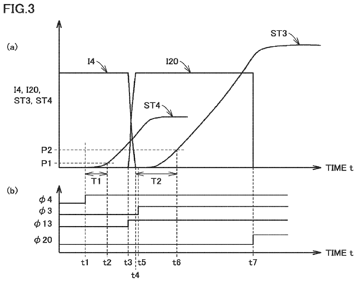
[0056]In the first embodiment, vacuum circuit breaker 4 is made nonconductive to allow the direct current to be commutated to semiconductor switch 20, gas disconnector 3 is then made nonconductive, and thereafter semiconductor switch 20 is made nonconductive. In this way, the DC circuit breaker is made nonconductive.
[0057]Namely, as shown in FIG. 3, vacuum circuit breaker 4 is caused to start the opening operation (time t1), the two contacts of vacuum circuit breaker 4 are then disconnected from each other (time t2), accordingly gas disconnector 3 is caused to start the opening operation (time t5), the two contacts of gas disconnector 3 are then disconnected from each other (time t6), and accordingly semiconductor switch 20 is made nonconductive (time t7). In this way, the DC circuit breaker is made nonconductive.
[0058]However, time T1 (time t1 to t2) from the start of the opening operation of vacuum circuit breaker 4 to the disconnection of its two contacts differs from time T2 (ti...
third embodiment
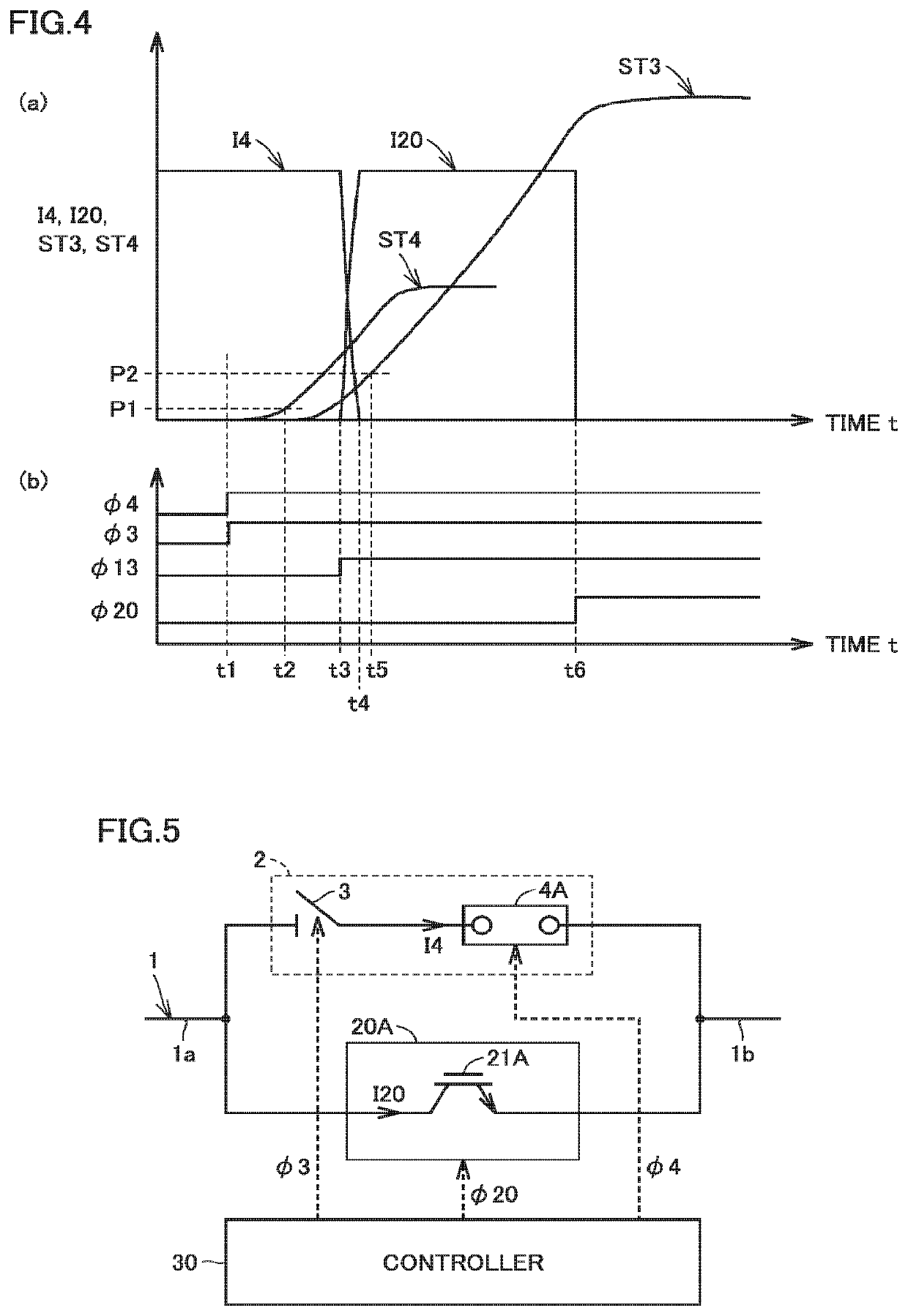
[0062]FIG. 5 is a circuit block diagram showing a configuration of a DC circuit breaker in a third embodiment of the present invention, which is to be contrasted with FIG. 1. Referring to FIG. 5, this DC circuit breaker differs from the DC circuit breaker in FIG. 1 in that vacuum circuit breaker 4 is replaced with a gas circuit breaker 4A, semiconductor switch 20 is replaced with a semiconductor switch 20A, and forced commutating circuit 10 is eliminated. In gas circuit breaker 4A, an insulating arc-extinguishing medium such as SF6 gas, nitrogen, argon, air, carbon dioxide, or the like fills the space between electrodes.
[0063]When gas circuit breaker 4A is caused to perform the opening operation, an arc is generated between its contacts and a higher arc voltage than vacuum circuit breaker 4 is obtained. Semiconductor switch 20A includes an IGBT 21A formed of SiC. IGBT 21A has a relatively low ON voltage. It is therefore possible to make the arc voltage of gas circuit breaker 4A suff...
PUM
| Property | Measurement | Unit |
|---|---|---|
| voltage | aaaaa | aaaaa |
| zero current point | aaaaa | aaaaa |
| current | aaaaa | aaaaa |
Abstract
Description
Claims
Application Information
 - R&D
- Intellectual Property
- Life Sciences
- Materials
- Tech Scout
- Unparalleled Data Quality
- Higher Quality Content
- 60% Fewer Hallucinations
Browse by: Latest US Patents, China's latest patents, Technical Efficacy Thesaurus, Application Domain, Technology Topic, Popular Technical Reports.
© 2025 PatSnap. All rights reserved.Legal|Privacy policy|Modern Slavery Act Transparency Statement|Sitemap|About US| Contact US: help@patsnap.com


