Autoloading screwdriver apparatus

a screwdriver and screw technology, applied in the field of screwdrivers, can solve the problems of unfavorable manual placement, screw dropping, magnetic material not holding the screws, etc., and achieve the effect of reducing the risk of undesirable screw separation

Active Publication Date: 2022-05-24
BIO MED PRO LLC
View PDF14 Cites 1 Cited by
  • Summary
  • Abstract
  • Description
  • Claims
  • Application Information

AI Technical Summary

Benefits of technology

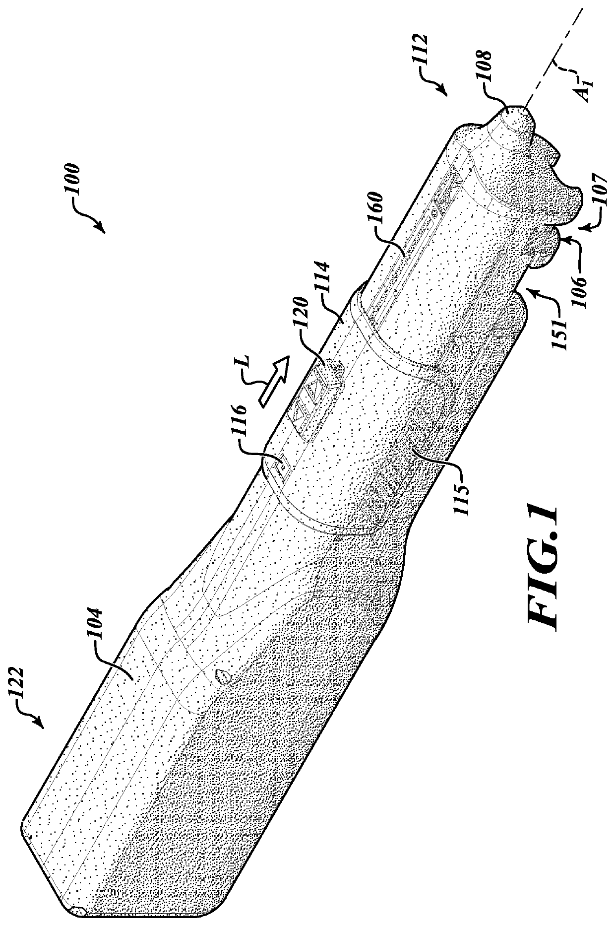
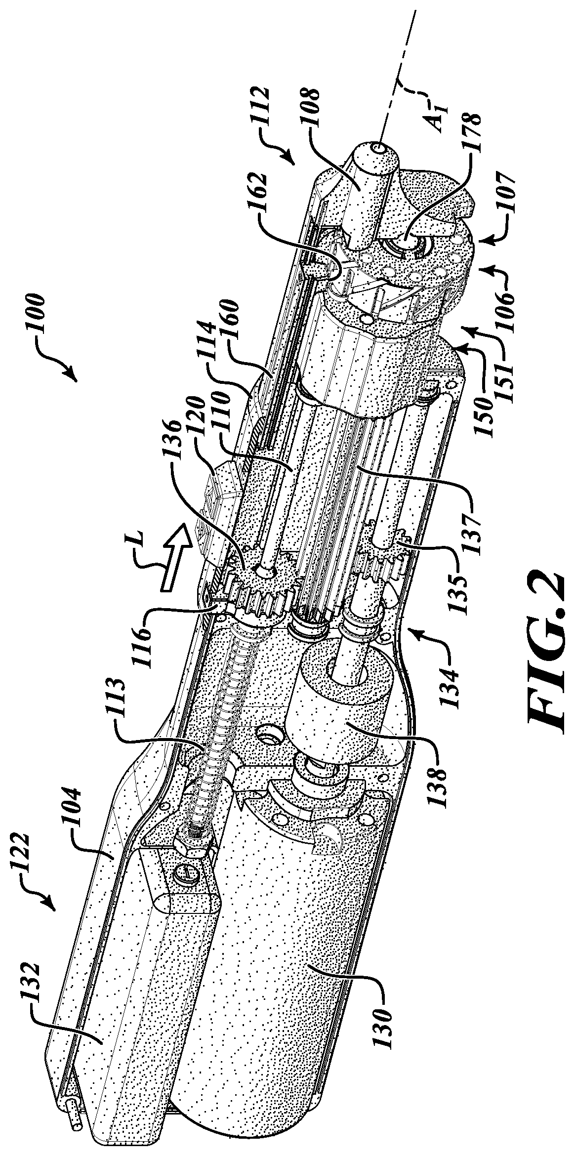
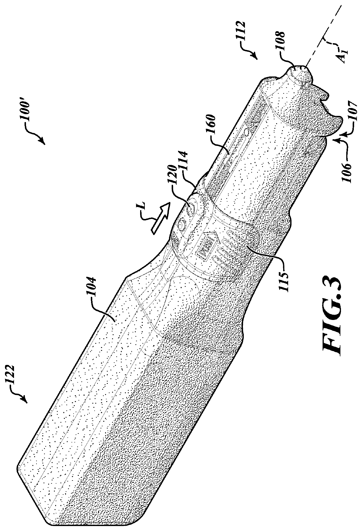
[0010]The autoloading screwdriver apparatuses, removable screw and tool cartridges thereof and other components and related methods shown and described herein provide autoloading screwdriver form factors that are robust, efficient, and particularly effective at driving screws with precision and reduced risk of undesirable separation of the screws from a driver thereof. Embodiments enable a user to avoid manually loading screws at the end of a driver and enable the user to displace screws from a loaded screw cartridge to a target site with relative ease.
[0017]The driver may be part of a driver assembly, and the driver assembly may include a return spring to bias the driver toward an aft position to enable the driver to return from an advanced position to the aft position under the bias of the return spring. The handle grip may be displaceable toward the working end by manually overcoming the bias of the return spring. The bias of the return spring may assist in rotating the screw cartridge to a next one of a plurality of incremental rotational positions as the driver retreats to the aft position to position another screw in working alignment with the driver. The driver assembly may be coupled to the handle grip to move longitudinally in unison therewith, and the driver may be supported by a rotational bearing fixedly coupled to the handle grip to enable the driver to rotate about a longitudinal driver axis upon manipulation of the control element by the user.

Problems solved by technology

A problem with this type of screwdriver is when the screw is not ferromagnetic, like titanium screws in a medical application, the magnetic material will not hold the screws using magnetic force.
A problem with this type of screwdriver is fixing the screw on the screwdriver head at the beginning and the possibility of dropping the screw if the screw becomes detached from the screwdriver head because the friction is insufficient to keep the screw in place.
However, for repeated, manual applications of the same screw sizes to a screw application job, this manual placement is not convenient and requires careful coordination of the screw to the materials and to the screwdriver to ensure the screw is applied to the right area of the material and at the right angle, typically perpendicular to the material to receive the screw.
However, the inconvenience and level of coordination increases significantly when the screws become smaller relative to the fingers of the user.
Since the screws are typically made of titanium (non-magnetic), it is not possible to use magnetic screwdrivers.
This requirement for tight tolerances not only increases the cost of manufacturing the screws and screwdrivers, but also makes picking up and handling the screws very difficult and risky (since the mechanical bond may be insufficient).
The tight mechanical bond does not prevent dropping the expensive, tiny screws.
It only reduces the chance of such a separation.
Conventional electric screwdrivers help surgeons to drive the screw into place, but have the additional risk of spinning off the screws and flinging them around to where they cannot be seen easily due to their tiny size.
These tiny screws can end up in the patient's open wound, which could be disastrous if the screws remain there after the operation is completed.
Therefore, another problem with the manual loading process is that it is very time consuming.
Neurosurgeons experience additional time lost and frustration due to screw drops.
As a result, use of conventional screwdrivers for neurosurgeons has drawbacks and shortcomings.
Thus, while an operator today has several alternatives for loading and applying screws, each has limitations.

Method used


Image

  • Autoloading screwdriver apparatus
  • Autoloading screwdriver apparatus
  • Autoloading screwdriver apparatus

Examples


Embodiment Construction

[0027]In the following description, certain specific details are set forth in order to provide a thorough understanding of various disclosed embodiments. However, one skilled in the relevant art will recognize that embodiments may be practiced without one or more of these specific details. In other instances, well-known devices, structures and techniques associated with screwdrivers, components thereof and related methods of driving screws may not be shown or described in detail to avoid unnecessarily obscuring descriptions of the embodiments.

[0028]Unless the context requires otherwise, throughout the specification and claims which follow, the word “comprise” and variations thereof, such as “comprises” and “comprising,” are to be construed in an open, inclusive sense, that is, as “including, but not limited to.”

[0029]Reference throughout this specification to “one embodiment” or “an embodiment” means that a particular feature, structure or characteristic described in connection with...


PUM


Abstract

An autoloading screwdriver apparatus is provided which includes a base; a screw cartridge received by the base; a driver supported within the base that is selectively engageable with a screw of the screw cartridge by manually displacing the driver toward a working end of the autoloading screwdriver apparatus; and a handle grip movably coupled to the base and configured to be manually displaced in a longitudinal direction toward the working end of the autoloading screwdriver apparatus to move the driver into engagement with the screw and to displace the screw to the working end of the autoloading screwdriver apparatus for presenting the screw to be screwed into a target substrate. The autoloading screwdriver apparatus may further include a control element manipulable by a user to activate rotational movement of the driver to drive the screw into the target substrate.

Description

BACKGROUNDTechnical Field[0001]The present disclosure relates generally to screwdrivers and, more specifically, to autoloading screwdrivers that allow a user to load screws on a driver thereof without having to manually place or hold a screw on the driver head or rely on pretensioned screw holding cartridges or complex electronic control systems. Such autoloading screwdrivers may be particularly well suited for installing screws in surgical applications.Description of the Related Art[0002]In a number of applications, a person wishing to place screws into a material must manually place screws at the head of a screwdriver and hold the screw in place against a material to receive the screw and against the screwdriver. Some screwdrivers are made of ferromagnetic material, so that when using a screw made of material attracted to magnetic materials, the screw generally will remain attached to the screwdriver. A problem with this type of screwdriver is when the screw is not ferromagnetic, ...

Claims


Application Information

Patent Timeline
Patent Type & Authority Patents(United States)
IPC IPC(8): A61B17/88B25B23/06A61B17/86
CPCA61B17/8875A61B17/865B25B23/06
Inventor NASR, MICHAEL
Owner BIO MED PRO LLC
Why Eureka
Try Eureka