
Oxygen generation check valve device

a technology of oxygen or nitrogen and check valve, which is applied in the direction of functional valve types, separation processes, transportation and packaging, etc., can solve the problems of mechanical effort in the process of scrubbing oxygen or nitrogen from air, inconvenient use of scrubbing media, and inconvenient us

Active Publication Date: 2022-05-24
O2 AIR SEA LLC
View PDF18 Cites 0 Cited by
  • Summary
  • Abstract
  • Description
  • Claims
  • Application Information

AI Technical Summary

Benefits of technology

This patent is about a new design for a bracket system that can be used in gas concentrating systems. The bracket system has check valves that are compressed and made with metal or plastic materials. These valves have two-axis orifice passages that allow for simultaneous and efficient oxygen concentration and nitrogen scrubbing of sieve beds. The design also reduces the need for many electromechanical components, resulting in a more energy-efficient and cost-effective PSA system. Additionally, the bracket system can be used in existing gas concentrating systems to improve their performance and save maintenance and lifecycle costs. Overall, this invention provides a more efficient and cost-effective solution for gas concentration and production.

Problems solved by technology

The process of scrubbing oxygen or nitrogen from air is a mechanical effort and requires electro-mechanical components in order to do so.
In order to concentrate oxygen, nitrogen and other gases as efficiently and cost effectively as possible has been a challenge and goal of institutions and industry for many decades.
It is impractical and not cost effective to use a scrubbing media such as zeolite for a one-time pass-through process whereby it has absorbed nitrogen to the point it can no longer scrub sufficient quantities and as such has to be discarded.

Method used


Image

  • Oxygen generation check valve device
  • Oxygen generation check valve device
  • Oxygen generation check valve device

Examples


Embodiment Construction

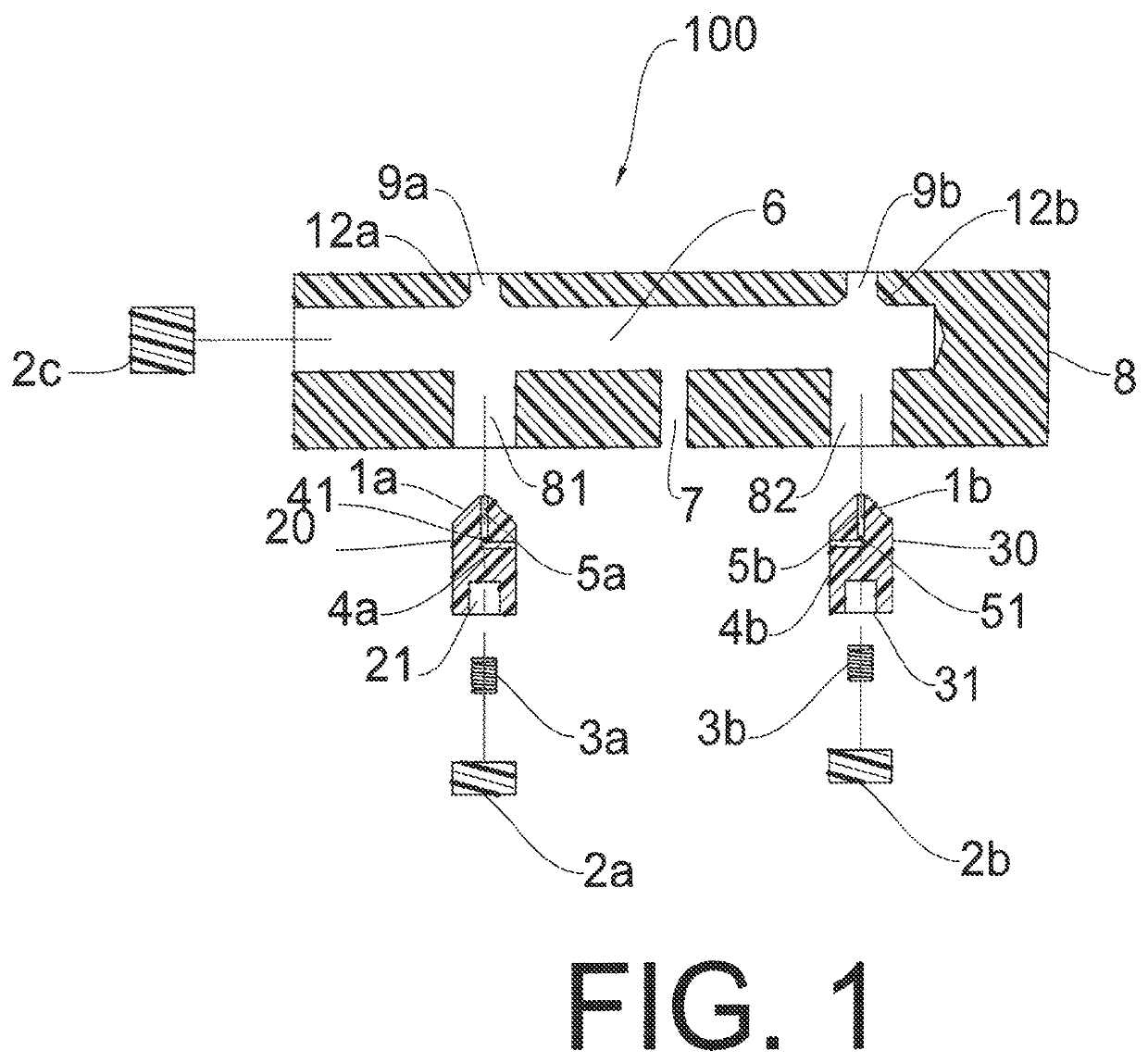
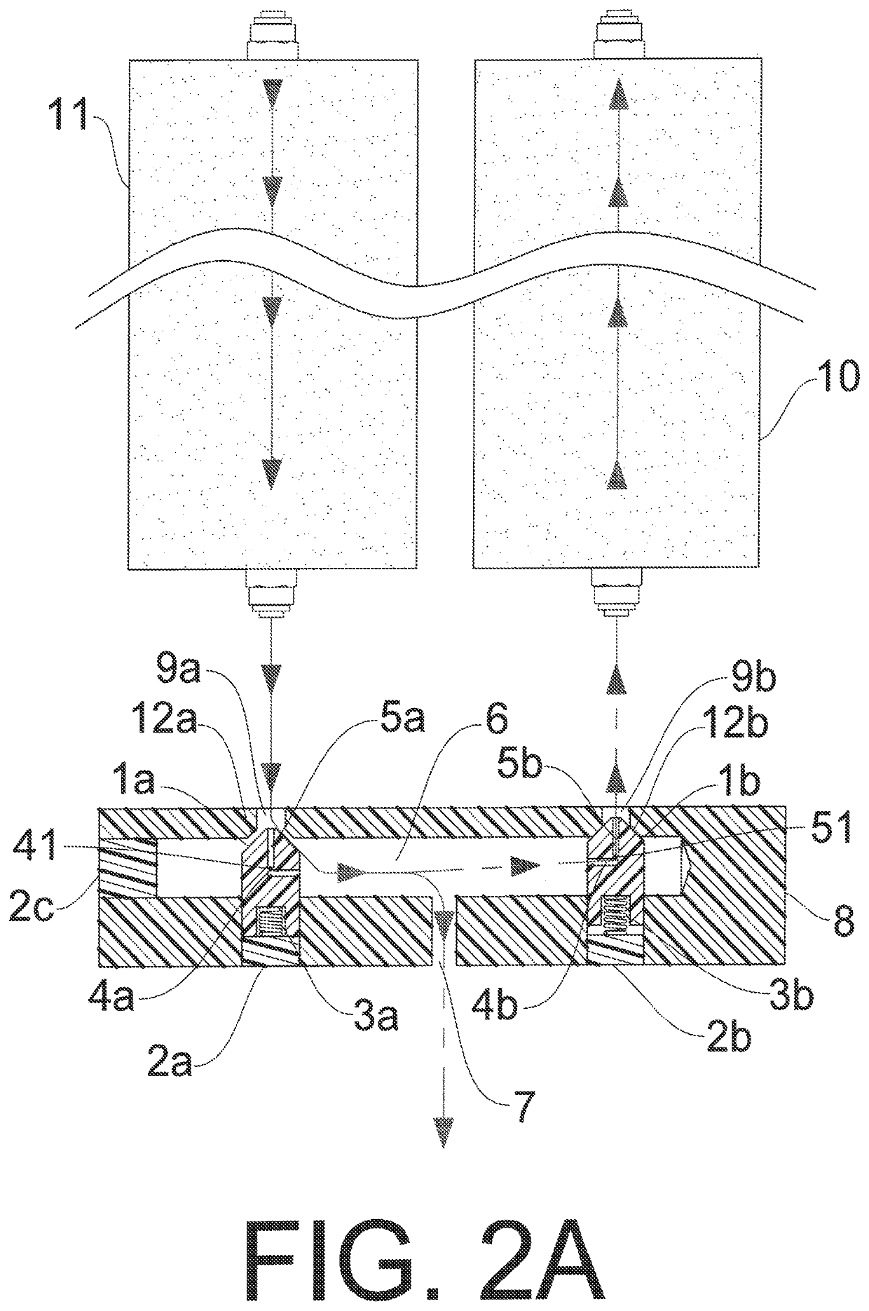
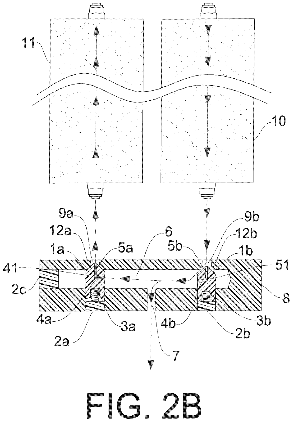
[0018]FIGS. 1-10 illustrate a check valve device 100 that controls a flow of air, nitrogen, and oxygen from a scrubbing sieve bed and outputs oxygen. The check valve device 100 includes a header 8, at least one check valve plunger 20, 30, and at least one compression device 3a, 3b.

[0019]The header 8 has an internal channel 6, at least one inlet-outlet port 9a, 9b, an outlet port 7, and at least one plunger port 81, 82. The header 8 can be integrally formed as a single component. The header 8 can be a housing, combined with a housing, integrally formed with a housing, or combined with a housing or other components. The header can have any exterior shape to meet the requirements of a specific application or system, including a shape selected from a square, a rectangle, a cylinder, a shape having at least three exterior sides or surfaces, and any combination thereof. The sides or surfaces can be flat, curved, or a combination thereof. The internal channel 6 is in direct communication ...


PUM


Abstract

A gas check valve device having a header, at least one check valve plunger, at least one orifice that provides a first path for a small amount of gas to pass through the at least one check valve plunger when a respective compression spring presses the check valve plunger against a check valve seat to form an air tight seal, and a common gas passage connecting the check valve plunger with a common outlet. The gas check valve device provides a second path for a small amount of gas to pass through the orifice of the at least one check valve plunger in a reverse direction and a larger amount of the gas to pass between the at least one check valve plunger and the check valve seat when the gas pressure compresses the respective compression spring to separate the check valve plunger from the check valve seat.

Description

BACKGROUND OF THE INVENTIONField of the Invention[0001]This invention relates to components and systems commonly used to concentrate gases that is used in a multitude of industries such as manufacturing, medical, environmental, hydroponics, and marine environments.Description of the Related Art[0002]Many industrial, health and environmental benefits are obtained through the utilization of highly purified or concentrated gases such as oxygen or nitrogen. The process of scrubbing oxygen or nitrogen from air is a mechanical effort and requires electro-mechanical components in order to do so. In order to concentrate oxygen, nitrogen and other gases as efficiently and cost effectively as possible has been a challenge and goal of institutions and industry for many decades. A common gas production method used to concentrate oxygen or nitrogen gas is a process called passive swing absorption, or PSA. PSA is a process whereby air, naturally containing approximately 20.9% oxygen, is compresse...

Claims


Application Information

Patent Timeline
Patent Type & Authority Patents(United States)
IPC IPC(8): F16K17/04
CPCF16K17/04Y10T137/7847Y10T137/7848Y10T137/7849F16K2200/401F16K11/105F16K15/025B01D2259/40003
Inventor MAXWELL, JOHNNYOWENS, MARK
Owner O2 AIR SEA LLC
Learn More