Check patentability & draft patents in minutes with Patsnap Eureka AI!

Method and system for cranking an internal combustion engine

a technology of internal combustion engine and cranking system, which is applied in the direction of engine starters, machines/engines, electric generator control, etc., can solve the problems of affecting the operation of the isg system, prone to failure, and occupying space inside the engine casing,

Active Publication Date: 2022-05-31
SEDEMAC MECHATRONICS PVT
View PDF30 Cites 0 Cited by
  • Summary
  • Abstract
  • Description
  • Claims
  • Application Information

AI Technical Summary

Benefits of technology

This approach enables reliable cranking of the internal combustion engine without the need for sensors, reducing costs and space requirements, while improving the system's resilience to harsh conditions and wire damage.

Problems solved by technology

Since such sensors are placed inside engine casing, they are subjected to harsh operating conditions such as high temperature and vibrations, which make them prone to failure.
Further, a special arrangement is required for mounting the sensors which adds cost and occupies space inside the engine casing.
Further, any damage to wires impairs operation of the ISG system.

Method used


Image

  • Method and system for cranking an internal combustion engine
  • Method and system for cranking an internal combustion engine
  • Method and system for cranking an internal combustion engine

Examples


Embodiment Construction

[0018]The present invention is directed to a method and a system for cranking an internal combustion engine coupled to a permanent magnet machine.

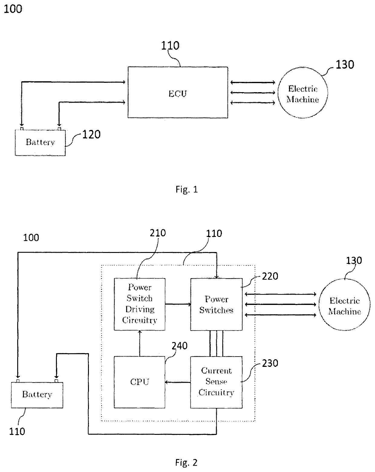
[0019]FIG. 1 illustrates a schematic view of a system 100 for controlling an electric machine 130 to achieve a desired cranking of an internal combustion engine in accordance with an embodiment of the invention. The permanent magnet machine includes a rotor having a plurality of permanent magnets poles, and a stator having a plurality of phase windings disposed on the stator, each phase winding including a plurality of coils,

[0020]As shown, a control unit 110 is connected to a power supply 120 and the electric motor 130. In this regard, the control unit may be a dedicated or an onboard Electronic Control Unit (ECU) of a vehicle. The power supply may be a battery of the vehicle.

[0021]Based on various inputs in the form of voltage, current, speed of the electric motor, etc, received by the ECU, the ECU determines position of the rotor and fu...


PUM


Abstract

The invention relates to a method for cranking an internal combustion engine, including the steps of: (a) receiving a start signal; (b) determining an initial position of the rotor with respect to a stator phase winding; (c) applying a pulse-width-modulated signal to the stator winding corresponding to determined initial position of the rotor; (d) determining a threshold value of the stator current variation; (e) measuring current of the stator winding in response to applied pulse-width-modulated signal to determine current variation; (f) if current variation is more than the threshold value, determining updated rotor position, applying a pulse-width-modulated signal to the stator winding corresponding to the updated rotor position; and repeating steps (d)-(f); and (g) if current variation is less than the threshold value, applying a pulse-width-modulated signal to the stator winding corresponding to the last updated rotor position and repeating steps (d)-(g).

Description

FIELD OF THE INVENTION[0001]The invention relates to cranking an internal combustion engine and more particularly to method and system for cranking an internal combustion engine coupled to a permanent magnet machine.BACKGROUND OF THE INVENTION[0002]An Integrated Starter Generator (ISG) system is generally used for the purpose of starting an Internal Combustion (IC) engine and for electric power generation. Typically an ISG system has a single electric machine connected to a crankshaft of a vehicle. For starting of IC engine, the electric machine is rotated which in turn rotates the crankshaft. Such rotation should be at a sufficiently high speed before the self-sustaining combustion process can commence inside the IC engine. During a power generation operation, crankshaft rotates the electric machine to generate electric power required to charge a battery and power other electrical loads of the vehicle.[0003]In a conventional ISG system, an electronic control unit (ECU) is placed be...

Claims


Application Information

Patent Timeline
Patent Type & Authority Patents(United States)
IPC IPC(8): H02P6/00H02P6/20F02N11/08H02P6/185
CPCH02P6/20F02N11/08H02P6/185F02N2200/022F02N2200/044F02N2200/063H02P2207/05F02N11/02F02N11/04F02N11/087H02P9/08
Inventor ANAYKUMAR, JOSHIAMIT, DIXIT
Owner SEDEMAC MECHATRONICS PVT
Features
  • R&D
  • Intellectual Property
  • Life Sciences
  • Materials
  • Tech Scout
  • Unparalleled Data Quality
  • Higher Quality Content
  • 60% Fewer Hallucinations
Learn More