
Autonomous cardiac implant of the leadless capsule type, including a piezoelectric beam energy harvester

a leadless capsule, energy harvester technology, applied in the direction of generator/motor, diagnostic recording/measuring, therapy, etc., can solve the problems of maximum beam bending force, inability to use a conventional battery, and detriment of reliability

Active Publication Date: 2022-06-14
CAIRDAC
View PDF19 Cites 2 Cited by
  • Summary
  • Abstract
  • Description
  • Claims
  • Application Information

AI Technical Summary

Problems solved by technology

The life duration of such an implant being of about 8 10 years, taking into account the very small dimensions, it is not possible to use a conventional battery, even a high-density one.
Many technical difficulties have however to be solved to allow making PEHs that are, despite an extreme miniaturization, both extremely performing and perfectly reliable, with typically a life time without failure nor loss of efficiency of at least 10 years.
Experience shows in particular that one of these difficulties occurs critically at the clamping of the transducing beam, where the stress of the beam in its bending movement is maximum.
The way the beam is clamped into the part that supports it and connects it to the capsule body is therefore a particularly tricky aspect of the design and making of a PEH, and consequently, of an efficient and reliable leadless implant.
not too high, as an excessive stress would be to the detriment of the reliability.
Moreover, the technical solutions involving bondings are to be avoided, because they are in the long term subject to oxidation and ageing phenomena, which hardly guarantee the absolute reliability required for this type of implanted devices.
However, these solutions are complex to industrialise as regards the mechanical manufacturing and the size tolerances of the different parts, hence expensive to implement.
Moreover, the plastic material parts or the overmouldings remain very sensitive to ageing of the material in the very long term, hence they do not offer an absolute guarantee of the required reliability for a device implanted in the organism.

Method used


Image

  • Autonomous cardiac implant of the leadless capsule type, including a piezoelectric beam energy harvester
  • Autonomous cardiac implant of the leadless capsule type, including a piezoelectric beam energy harvester
  • Autonomous cardiac implant of the leadless capsule type, including a piezoelectric beam energy harvester

Examples


Embodiment Construction

[0067]An exemplary embodiment of the device of the invention will now be described, in an application to an autonomous implantable capsule intended to be implanted into a cardiac cavity.

[0068]As indicated hereinabove, this particular application is not limitative of the invention, whose teachings may be applied to many other types of autonomous devices incorporating an energy harvester of the PEH type, whether these devices are implantable or not, medical or not.

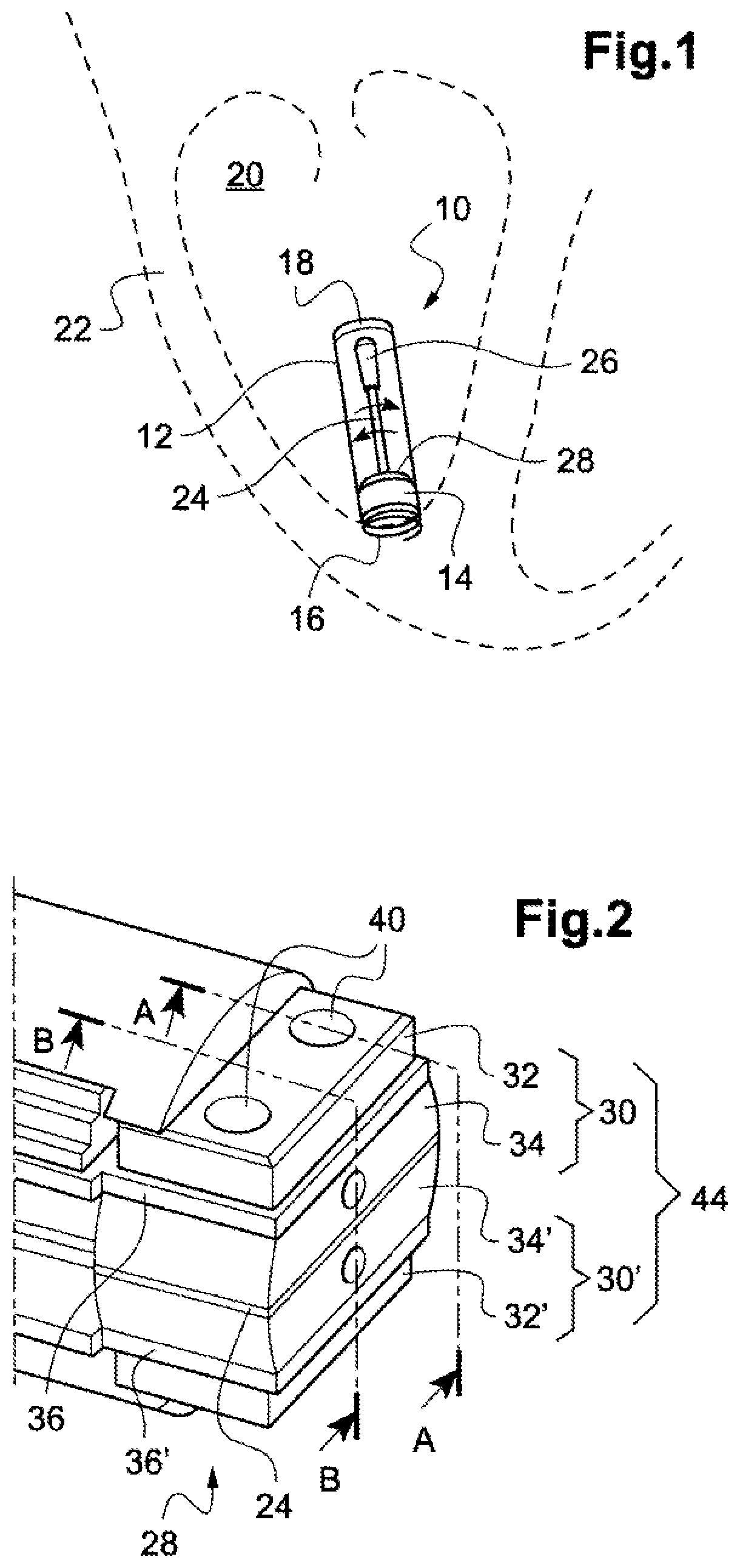
[0069]FIG. 1 shows a leadless capsule device 10 in a cardiac stimulation application.

[0070]The capsule 10 is made in the external form of an implant with an elongated cylindrical tubular envelope 12 enclosing the various electronic and power supply circuits of the capsule, as well as an energy harvester with a pendular unit. The typical dimensions of such a capsule are a diameter of the order of 6 mm for a length of about 25-40 mm.

[0071]The tubular envelope 12 has, at its front (distal) end 14, a protruding anchoring element...


PUM


Abstract

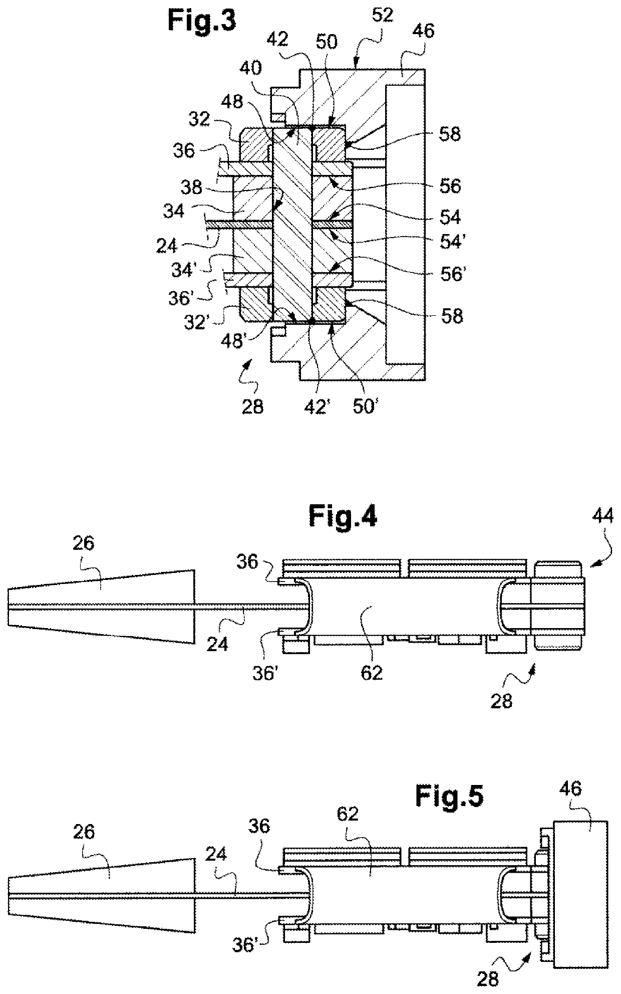
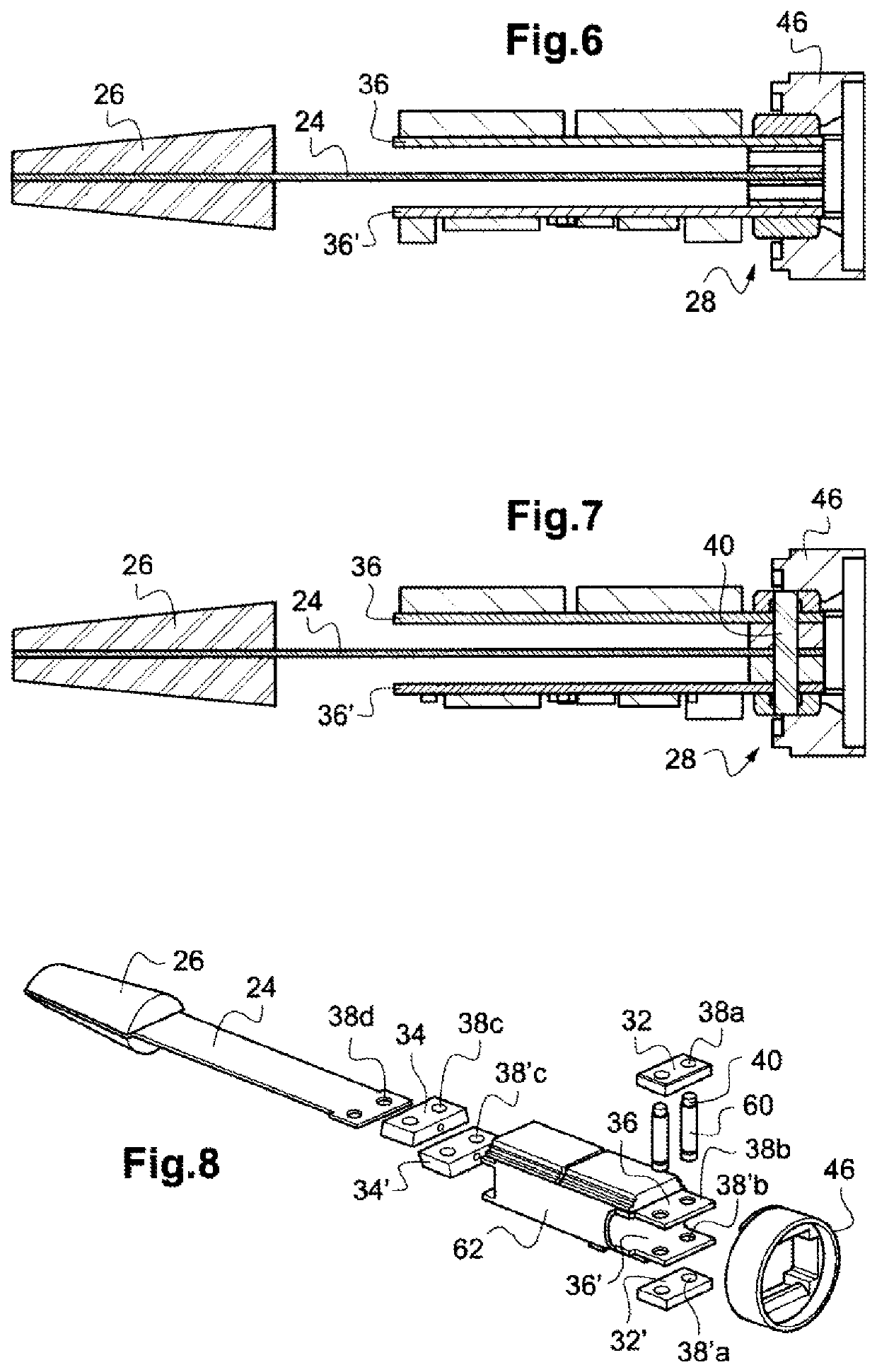
An energy harvester includes a pendular unit subjected with a piezoelectric beam coupled to an inertial mass. On the clamped side of the beam, a beam frame includes two pressing elements between which the beam is taken in sandwich, each including i) an intermediate part, an internal face of which presses on a corresponding face of the beam, and ii) a pressure plate, an internal face of which presses on an external face of the intermediate part, a printed circuit board being interposed between them. The intermediate parts and the pressure plates are passed through by at least one common transverse bore receiving a locking pin. The intermediate parts, the pressure plates and the pin are each massive metal parts ensuring a direct electrical and mechanical contact with the electrodes of the beam and with the printed circuit boards.

Description

CROSS REFERENCE TO RELATED APPLICATIONS[0001]This application claims priority under 35 U.S.C. § 119(a) to European patent application number 20315142.8, filed on Apr. 9, 2020, the entire teachings of which are incorporated herein by reference.BACKGROUND OF THE INVENTIONField of the Invention[0002]The invention relates to energy harvesting devices, also called harvesters or scavengers, which collect mechanical energy resulting from various movements they undergo and convert this mechanical energy into electrical energy, and more particularly to the harvesting devices of the so-called “PEH” (Piezoelectric Energy Harvester) type, which use as a mechanical-electrical transducer an oscillating piezoelectric beam coupled to an inertial mobile mass.Description of the Related Art[0003]In the field of medical implants, the recent advances in miniaturization of active devices and the advances in life sciences allow from now on the development of a wide variety of fully autonomous, miniaturize...

Claims


Application Information

Patent Timeline
Patent Type & Authority Patents(United States)
IPC IPC(8): H02N2/18A61N1/378A61N1/375H01L41/113H02N2/00
CPCA61N1/3785A61N1/3756H01L41/1136H02N2/186H02N2/22A61N1/37205A61N1/057A61N1/3956A61B2560/0214A61B5/07A61B5/283H10N30/306A61B5/29
Inventor REGNIER, WILLYNGUYEN-DINH, AN
Owner CAIRDAC
Learn More