
Self-propelled work machine

Active Publication Date: 2022-06-14
LIEBHERR COMPONENTS BIBERACH GMBH
View PDF30 Cites 0 Cited by
  • Summary
  • Abstract
  • Description
  • Claims
  • Application Information

AI Technical Summary

Benefits of technology

The patent text describes the arrangement of a motor and wheel axes in a vehicle. The motor axis can be positioned in a skewed manner, which allows for a hypoid gear stage. This arrangement can be beneficial for increasing ground clearance and avoiding collisions with other machine components. The technical effect is improved design for electric vehicles.

Problems solved by technology

In comparison with hydrostatic drives, however, electric motors are a great deal larger with the same output power and thus also have a higher rotary inertia so that more energy has to be used during acceleration procedures.
This in turn results in worse efficiency when the energy used for acceleration cannot be reused.
In operation with frequent acceleration processes, the named disadvantages in efficiency result due to the relatively high inertia of the electric motor.
Such long, slim electric motors are, however, difficult to install in self-propelled work machines such as bulldozers which have a relatively narrow track width, in particular when single wheel drives or single track drives are used in which a respective separate electric motor drives a right wheel and a left wheel or chain wheel since the long, slim electric motors of such single-wheel drive arrangements stand in the way of one another or since there is not sufficient installation space available for such long, slim electric motors.

Method used


Image

  • Self-propelled work machine
  • Self-propelled work machine

Examples


Embodiment Construction

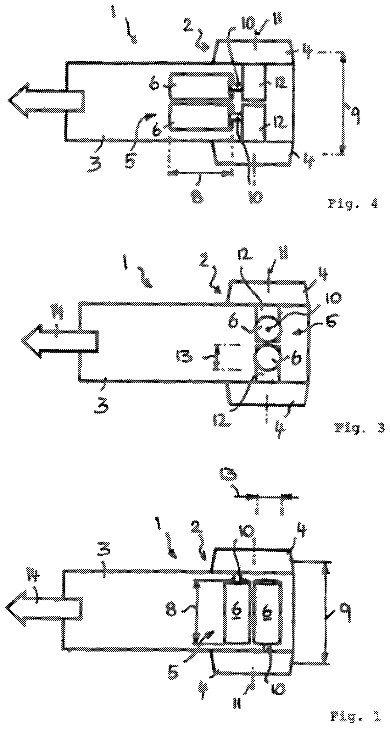
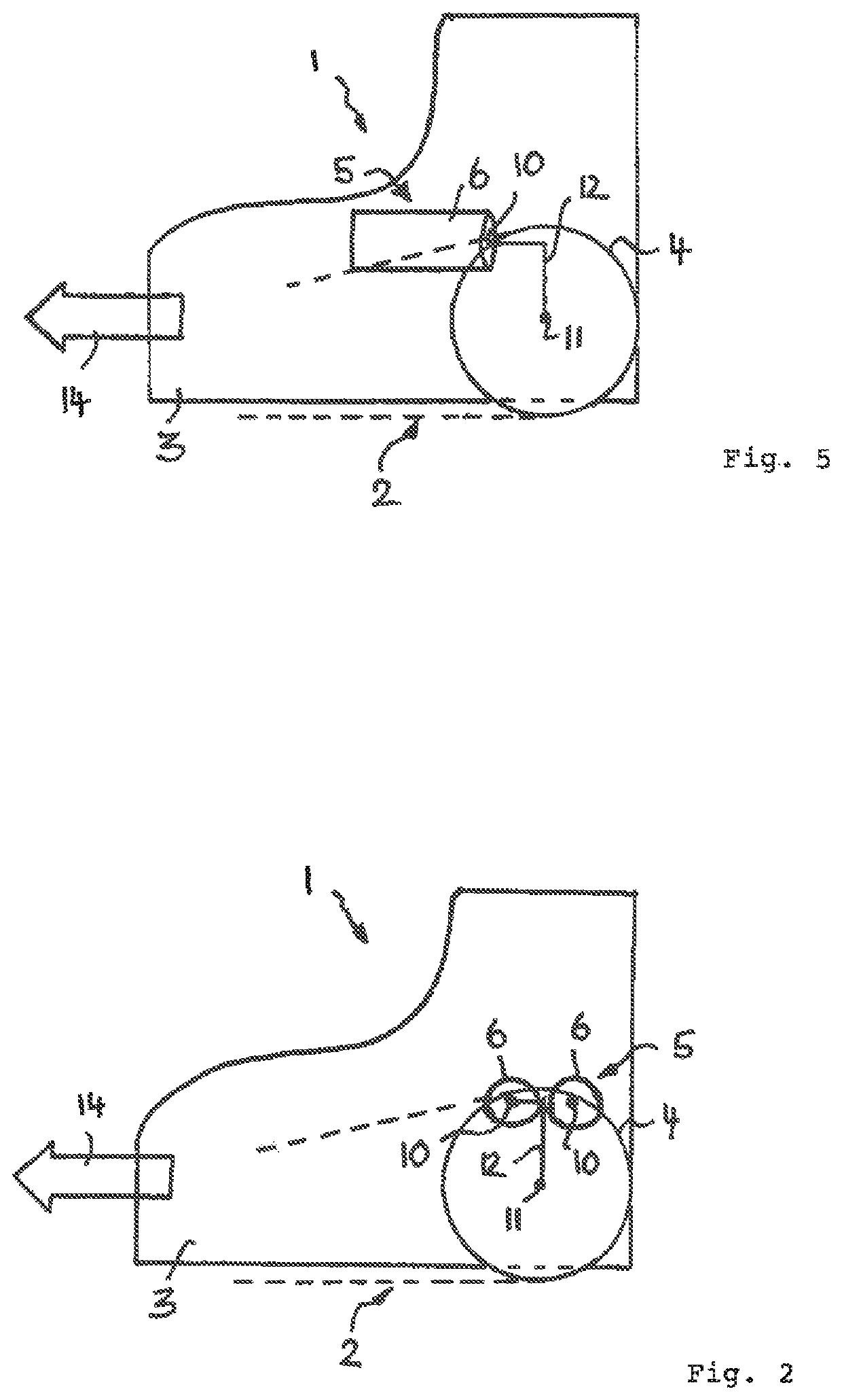
[0028]The self-propelled work machine only shown schematically in FIG. 1 can, for example, be a tracked vehicle, in particular a bulldozer 1, whose chassis can be formed as a tracked chassis 2 having a respective crawler track at the right and at the left of the machine body 3. The named crawler tracks can in this respect each be driven by means of a chassis wheel 4, in particular in the form of a chain wheel or of a sprocket, with the chassis wheels or chain wheels to be driven being able to be arranged mutually opposite at different sides of the machine body 3 such that they form a common chassis axis, cf. FIG. 1.

[0029]The travel drive 5 in this respect comprises single-wheel drives each having at least one electric motor 6 for driving a respective one of the named chassis wheels 4, with the named electric motors 6 being able to be connected to the respective chassis wheel 4 while interposing a gear stage.

[0030]As FIG. 1 shows, the named electric motors 6 are formed in a long slim...


PUM


Abstract

A self-propelled work machine, in particular a tracked vehicle, such as a bulldozer, having a traction drive comprising at least one electric motor for driving at least one chassis wheel, in particular a chain wheel or a sprocket. The motor axis of rotation of the electric motor is arranged displaced and / or angled with respect to the wheel axis of rotation of the chassis wheel to be driven by the electric motor.

Description

CROSS REFERENCE TO RELATED APPLICATIONS[0001]The present application is a U.S. National Phase of International Patent Application Serial No. PCT / EP2014 / 003163, entitled “Self-Propelled Machine,” filed on Nov. 26, 2014, which claims priority to German Utility Model Patent Application No. 20 2013 011 046.5, filed on Dec. 11, 2013, the entire contents of each of which are hereby incorporated by reference in their entirety for all purposes.TECHNICAL FIELD[0002]The present invention relates to a self-propelled work machine, in particular to a tracked vehicle such as a bulldozer, having a traction drive comprising at least one electric motor for driving at least one chassis wheel, in particular a chain wheel or a sprocket.BACKGROUND AND SUMMARY[0003]With self-propelled work machines such as bulldozers or similar tracked vehicles or also other self-propelled off-road vehicles for construction sites, mines and the like, electric drives having at least one electric motor have been used in mo...

Claims


Application Information

Patent Timeline
IPC IPC(8): B60K7/00B60K1/02H02K7/116B62D55/06B62D55/12E02F3/76
CPCB60K7/0007B62D55/06B62D55/12H02K7/116H02K7/1163B60K2007/0046B60K2007/0061B60K2007/0069B60K2007/0076B60K2007/0084B60Y2200/25B60Y2200/411E02F3/76B60K1/02
Inventor MUENST, THOMAS
Owner LIEBHERR COMPONENTS BIBERACH GMBH
Learn More