
Nonlinear optical devices with zig-zag beam paths

a beam path and optical device technology, applied in nonlinear optics, instruments, optics, etc., can solve the problems of not being practical for collinear phase-matching schemes, the use of huang design is limited to relatively thin solid-state nonlinear media, etc., to achieve the effect of improving the beam quality and improving the beam quality of optical parametric amplifier emission

Active Publication Date: 2022-06-14
JGM ASSOC
View PDF10 Cites 2 Cited by
  • Summary
  • Abstract
  • Description
  • Claims
  • Application Information

AI Technical Summary

Benefits of technology

[0027]An important problem in optical parametric oscillator-optical parametric amplifier design is “back-conversion” which acts to convert signal and idler emission back into pump emission. When back-conversion occurs, conversion efficiency is reduced, beam quality of optical parametric oscillator or optical parametric amplifier emission at the signal and idler wavelengths is usually degraded, and the signal and idler emission spectra may be broadened or changed in some important way. In general, the effects of back-conversion become more severe as optical parametric oscillator / optical parametric amplifier efficiency is increased and more output energy is generated at the signal and idler wavelengths for a given pump energy. For devices with millijoule-level pump and output energy, back-conversion typically results in optical parametric oscillator emission beam quality in the M2=10 to 20 range, and worse, and substantially reduced conversion efficiency. Mitigation of back-conversion is an important strategy for improving beam quality of optical parametric oscillators and optical parametric amplifiers that achieve high output energy.
[0030]Therefore, one strategy for reducing back-conversion in an optical parametric oscillator is to use a shorter optical parametric oscillator crystal in a shorter optical parametric oscillator resonator so that the resonated wave makes more bounces or reflections off the optical parametric oscillator mirrors during the pump pulse. Because a shorter optical parametric oscillator crystal length (length along the direction of the interacting beams) is being used, the non-resonated wave interacts with the resonated wave over a shorter distance before being dumped at one or both optical parametric oscillator mirrors, and the non-resonated wave cannot build to as high an intensity level as when a longer optical parametric oscillator crystal is being used. This situation may result in reduced back-conversion, which, in turn, may result in improved optical parametric oscillator conversion efficiency and, in some cases, somewhat improved beam quality for the emitted signal and / or idler beams.
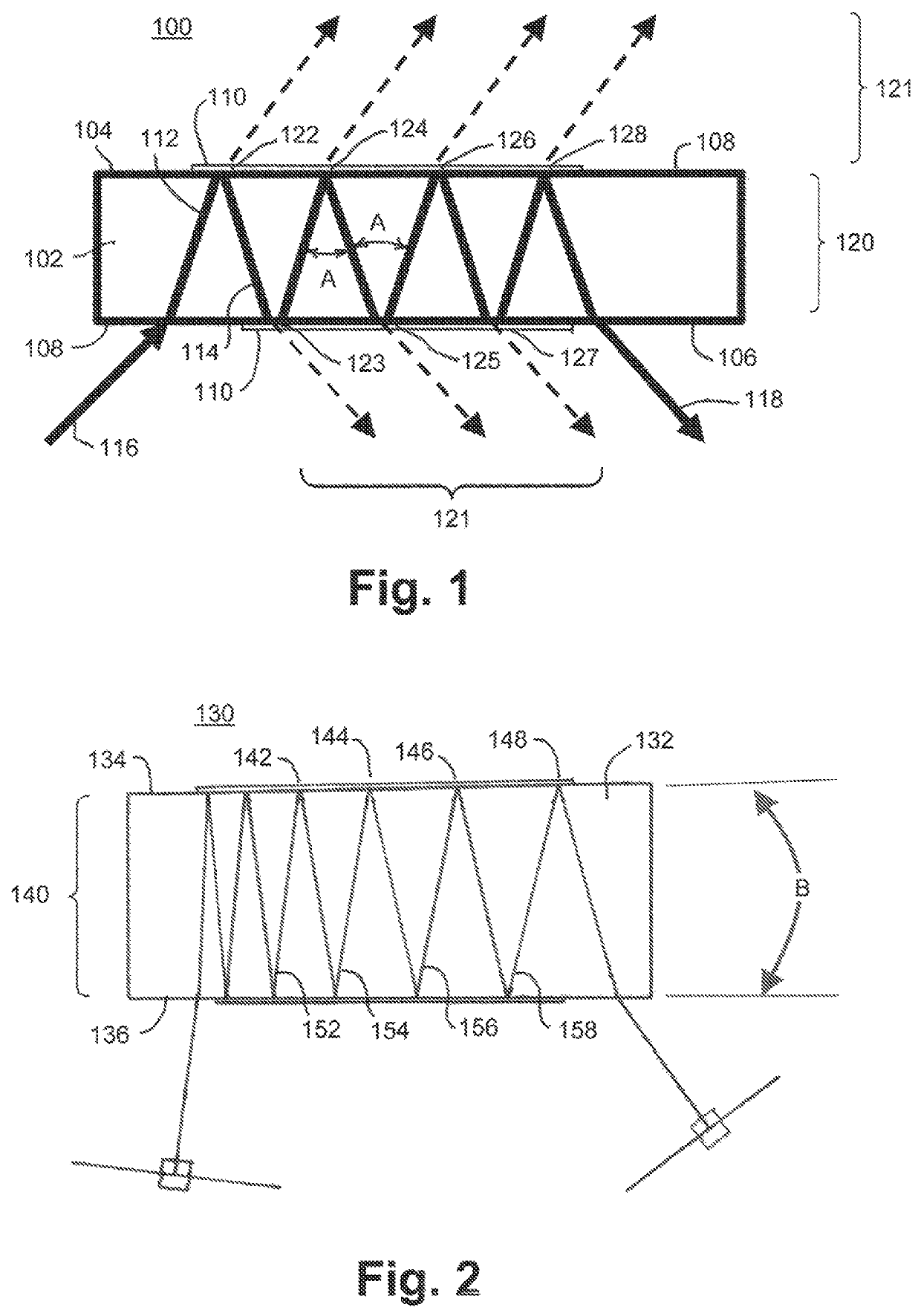
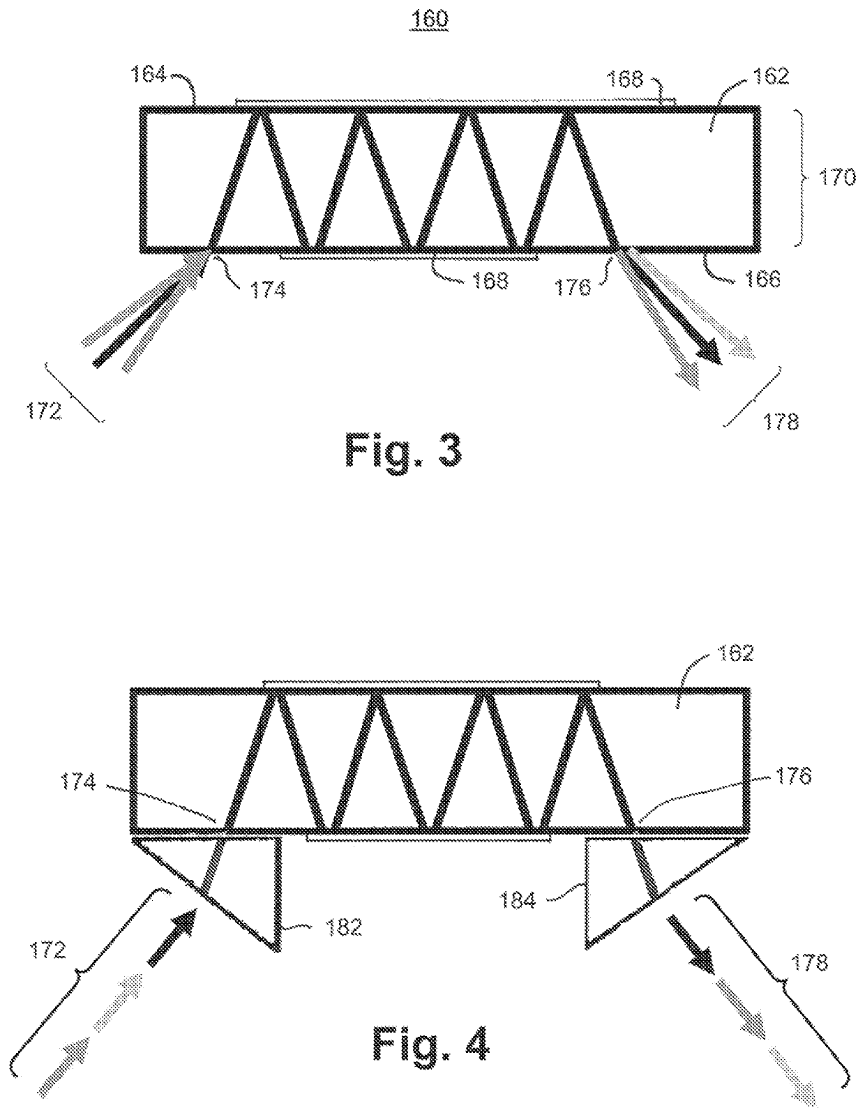
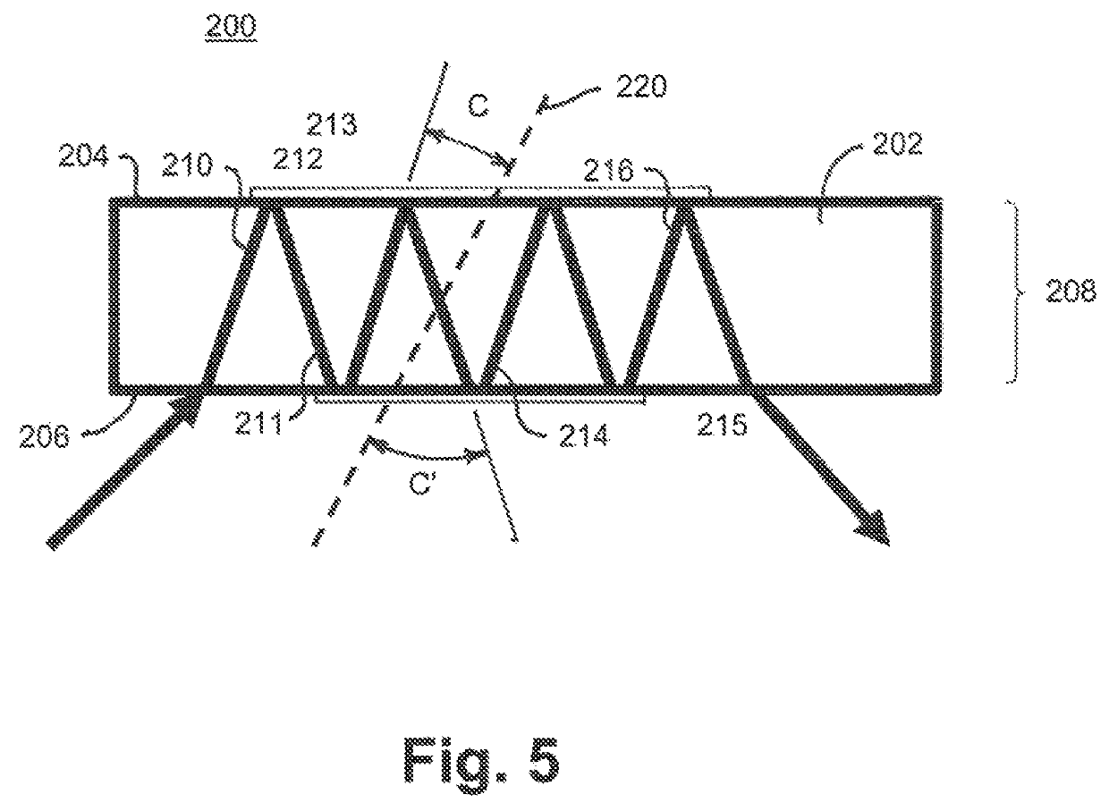
[0032]The present invention solves the above problem by configuring an optical parametric oscillator resonator in which the non-resonated wave can be dumped many more than two times for each round trip through the optical parametric oscillator resonator, and therefore many more times during the pump pulse. The non-resonated wave is never allowed to build to a high intensity as this may cause significant back-conversion when it interacts with the resonated wave. This is accomplished by controlling the number of reflections or bounces, leg lengths, and fold angles of the zig-zag path in the nonlinear medium, and by properly designing the dichroic coatings (or surface treatments) that establish the zig-zag path.
[0033]At the same time, by adjusting the separation distance between the mirrors of the optical parametric oscillator resonator configured around the nonlinear medium with zig-zag path, the resonator's Fresnel number can be made equal to one, or close to one, if one should desire such. That is, the zig-zag path and the optical parametric oscillator resonator's Fresnel number can be controlled independently as needed to mitigate back-conversion and improve beam quality.
[0034]Even though an optical resonator is not used, the invention can be applied with advantage in the design of optical parametric amplifiers. Beam quality of the optical parametric amplifier emission may be improved by designing the zig-zag beam path so that the dumped signal or idler wave (dumped at one or more bounce points) cannot build to a high intensity as needed to cause significant back-conversion when interacting with the amplified wave that is not being dumped.
[0036]In a stimulated Raman laser, for example, the dichroic coatings used to configure the zig-beam path may be designed to reflect pump emission and emission at the first-Stokes wavelength, but not emission at the second-Stokes wavelength. That is, the dichroic coating(s) would have little or no transmission at the pump and first Stokes wavelengths, but would be highly or partially transmitting at the second-Stokes wavelength. In this way, generation of light at the second-Stokes wavelength might be suppressed or prevented so that more pump light is emitted from the device at the first-Stokes wavelength. Alternatively, the dichroic coating(s) might have high reflectivity at the pump, first-Stokes, and second-Stokes wavelengths, and partial or high transmission at the third-Stokes wavelength, as a way to stop cascaded Raman generation beyond the second-Stokes wavelength.

Problems solved by technology

Accordingly, the Komine method is practically limited to use with relatively thin solid-state nonlinear media (thickness of 500 microns or less).
However, in the Huang method, the pump beam necessarily makes a straight-through pass in the nonlinear medium and does not follow a zig-zag beam path.
The Huang design may not be practical for use with collinear phase-matching schemes.

Method used


Image

  • Nonlinear optical devices with zig-zag beam paths
  • Nonlinear optical devices with zig-zag beam paths
  • Nonlinear optical devices with zig-zag beam paths

Examples


Embodiment Construction

[0070]The following detailed description is of the best currently contemplated modes of carrying out the invention. The description is not to be taken in a limiting sense, but is made merely for the purpose of illustrating the general principles of the invention. The detailed descriptions of embodiments provided below are intended only to be exemplary and explanatory and are not intended to be restrictive of, or on, the invention.

[0071]Unless indicated otherwise, “highly reflecting” indicates a high reflectivity value in the range of 95% R to 100% R at the wavelength in question, “partially reflecting (PR)” indicates a reflectivity in the range of 10% R to 95% R, “highly transmitting (HT)” indicates a transmission value in the range of 90% T to 100% T, and “partially transmitting (PT)” indicates a transmission in the range of 10% T to 90% T. However, in general, the terms HR, HT, PR, and PT are understood by someone well-versed in the art and the above definitions are not intended t...


PUM

PropertyMeasurementUnit
thicknessaaaaaaaaaa
anglesaaaaaaaaaa
angleaaaaaaaaaa

Abstract

The invention is an optical parametric oscillator or amplifier employing a zig-zag beam path, configured using dichroic mirrors or optical surfaces on the side-walls of a solid-state, liquid, or gaseous nonlinear medium, to control conversion efficiency, beam quality, or other aspects of the nonlinear conversion process by dumping unwanted radiation, the oscillator / amplifier for use with any nonlinear process in which it is advantageous to have one or more of interacting coherent beams be partially or fully transmitted at reflection points of the zig-zag path.

Description

CROSS REFERENCE TO RELATED APPLICATION[0001]The present Application is related to Provisional Patent Application entitled “Nonlinear Optical Devices with Zig-zag Beam Paths,” filed 16 Oct. 2018 and assigned filing No. 62 / 746,146, incorporated herein by reference in its entirety.FIELD OF THE INVENTION[0002]The invention relates to sources of coherent laser emission that use nonlinear optical methods to convert coherent light emission at one or more input wavelengths to coherent light emission at one or more output wavelengths. The invention employs a zig-zag beam propagation path, configured using dichroic thin-film or other dichroic optical coatings on one or more optical surfaces to control to some aspect of the wavelength conversion process. Such aspects might include emitted beam quality, the combination of wavelengths being generated, and conversion efficiency into a specific wavelength, among others.BACKGROUND OF THE INVENTION[0003]Nonlinear optical methods or processes are wid...

Claims


Application Information

Patent Timeline
Patent Type & Authority Patents(United States)
IPC IPC(8): G02F1/39G02F1/35
CPCG02F1/39G02F1/3501G02F1/3503G02F1/392
Inventor MANNI, JEFFREY G.
Owner JGM ASSOC
Learn More