Ultraviolet-free antiviral air-filtering lighting device

a technology of air-filtering and ultraviolet light, which is applied in the direction of lighting and heating equipment, lighting source combinations, fixed installations, etc., can solve the problems of uv light sources having uv is a potential health hazard, and uv light sources tend to have a shorter life span, so as to improve air-filtering efficiency and improve air processing capability. , the effect of improving the air-filtering efficiency

Active Publication Date: 2022-06-28
ALEDDRA INC
View PDF3 Cites 0 Cited by
  • Summary
  • Abstract
  • Description
  • Claims
  • Application Information

AI Technical Summary

Benefits of technology

[0008]The visible wavelength may not have as strong photon energy as UV wavelength. When using a visible light to activate a visible-light activatable photocatalyst material, it would be helpful to use other means to improvement the photocatalytic efficiency. One option is to increase the size of the surface area of the air filter coated with the photocatalyst material. Therefore, in some embodiments, the air filter comprises multiple layers or folds, which effectively increase the size of the surface area of the air filter coated with the photocatalyst material. In some other embodiments, the air filter is of cylindrical shape, which again help enlarging the surface area of the air filter coated with the photocatalyst material.
[0011]In some embodiments, the air circulation mechanism comprises at least one fan disposed in the airway. Another option to improve the air-filtering efficiency is the increase the air processing capability by using multiple fans. In some embodiments, the air circulation mechanism comprises a first fan and a second fan wherein the first fan sucks the ambient air into the airway and the second fan pulls the air out of the airway. This dual-fan configuration with a push (by the first fan) and a pull (by the second fan) of the air into and out of the airway, improves the air processing capability of the present disclosure, thus resulting a higher air-filtering efficiency.
[0012]In some embodiments, the first light source comprises light emitting diodes (LEDs) each emitting the first visible light. In some embodiments, the second light source comprises LEDs each emitting the second visible light. It is foreseeable to use a higher color temperature for the second light source because a higher color temperature tends to result in a higher light output, thus contributing to a higher photocatalytic efficiency, as compared to a light source with a lower color temperature.
[0013]In some embodiments, the first light source may further comprise a third light source and a fourth light source. Both emit predominantly visible lights (>400 nm), and the color temperature of the third light source is higher than the color temperature of the fourth light source. The use of the third light source with a higher color temperature is for providing a higher circadian stimulus, which is desirable for some lighting applications for mimicking the daylight. Similarly, the use of the fourth light source with a lower color is to provide a lower circadian stimulus for nighttime. Moreover, in some embodiments, the color temperature of the first light source may be tunable via a controller by mixing the combination ratio of color temperatures of the third light source and the fourth light source. This color tuning may be done manually, or it may be done automatically according to a circadian schedule stored in a memory module. The circadian schedule will transition the color temperature of the first light source from warm white (2700K) to cold white (6500K) at dawn and revert the color temperature back to warm white at sunset, thus emulating color transition of the sunlight.

Problems solved by technology

Firstly, UV is a potential health hazard since it causes skin and eye damages to an occupant.
If a UV-based second light source is not properly concealed in the airway, it may leak the UV wavelength into the environment.
Secondly, UV light source tends to have a shorter life span, between 2000-5000 hours.
Nonetheless, for an environment with an adequate light level provided by existing lighting fixtures, it would not be reasonable to use the present disclosure stated above without the intention of ever turning on the first light source.

Method used


Image

  • Ultraviolet-free antiviral air-filtering lighting device
  • Ultraviolet-free antiviral air-filtering lighting device
  • Ultraviolet-free antiviral air-filtering lighting device

Examples


example implementations

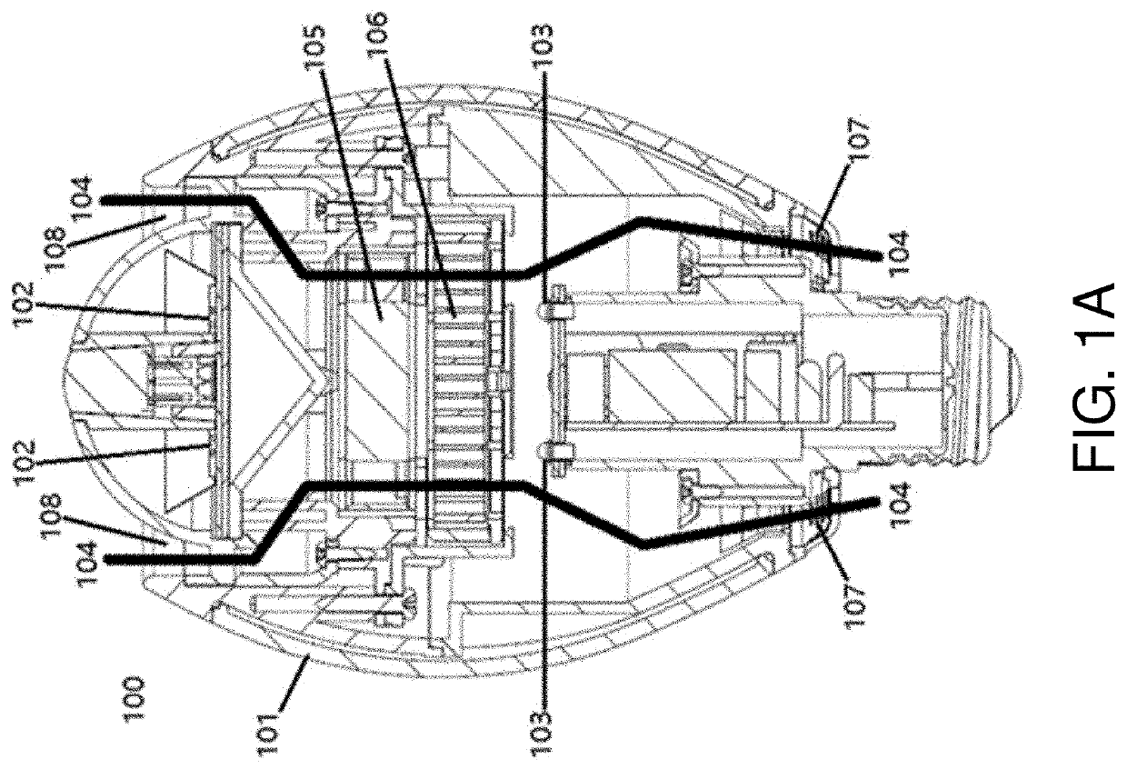
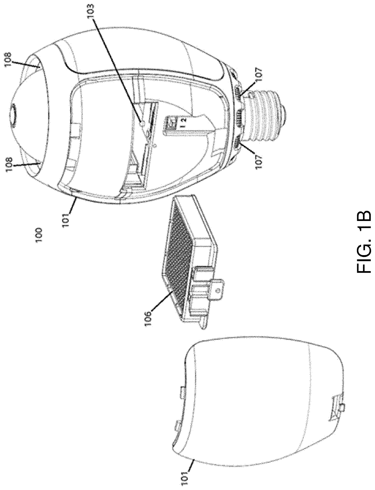
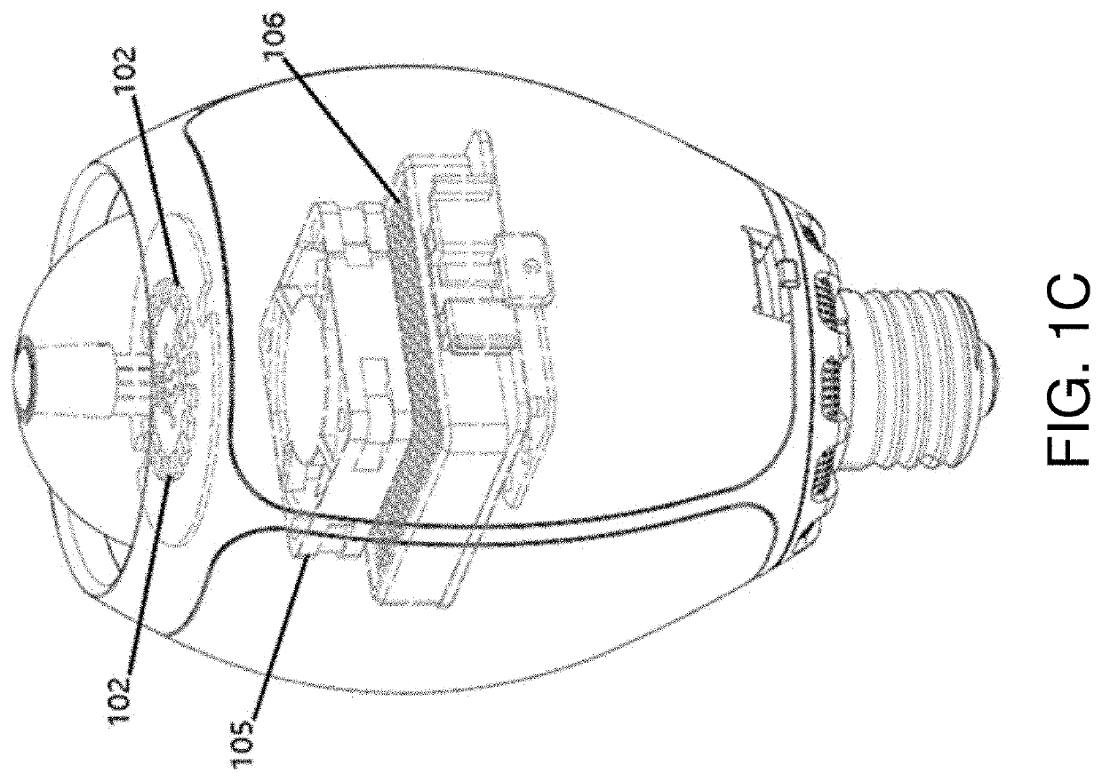
[0033]FIG. 1a-1c show an embodiment of the lighting device of the present disclosure in a form of an LED screw-in lamp 100. This lamp has a housing 101, the first light source 102, the second light source 103, one airway 104, and one fan 105 and one air filter 106. The first light source 102 comprises multiple LEDs on top of the lamp emitting predominantly white light in the >400 nm wavelength range, and accounts for 100% light output of the lighting device. The second light source 103 comprises multiple LEDs emitting predominantly white light in the >400 nm wavelength range, and they are concealed inside the housing and have no contribution to the light output of the lighting device. The airway 104 has an air inlet 107 and an air outlet 108. The fan 105 and the air filter 106 are disposed inside the airway 104. The fan 105 sucks the ambient air through the air inlet 107, forces the air through the air filter 106, and releases the air through the air outlet 108. The air filter 106 h...


PUM

PropertyMeasurementUnit
wavelengthaaaaaaaaaa
ultraviolet (UV) wavelengthaaaaaaaaaa
wavelength rangeaaaaaaaaaa

Abstract

A lighting device that comprises a housing, a first visible light source, a second visible light source, an air filter, an airway, and an air circulation mechanism for each airway. The first visible light source contributes to the light output of the device, whereas the second visible light source is responsible for germicidal irradiation by activating a visible-light activatable photocatalytic coating on the air filter. The airway has an air inlet and an air outlet. The air circulation mechanism sucks an ambient air through the air inlet, forces the air through the air filter, and releases the air through the air outlet. The air filter traps airborne particles. The second visible light source is disposed adjacent to the air filter and activates a photocatalyst material in the antiviral photocatalytic coating. Airborne microbials trapped by the air filter are decomposed by the activated photocatalyst material in the antiviral photocatalytic coating.

Description

CROSS-REFERENCE TO RELATED PATENT APPLICATION(S)[0001]The present disclosure is part of a Continuation-in-Part (CIP) of U.S. patent application Ser. No. 17 / 147,783, filed 13 Jan. 2021, which is a CIP of U.S. patent application Ser. No. 16 / 836,570, filed 31 Mar. 2020 and issued as U.S. Pat. No. 10,921,004 on 16 Feb. 2021, the contents of which being incorporated by reference in their entirety.BACKGROUNDDescription of Related Art[0002]In U.S. patent application Ser. No. 17 / 147,783, an antiviral air-filtering lighting device was introduced. The device includes a housing, a first light source, a second light source, an airway, an air filter, and an air circulation mechanism corresponding to the airway. The housing houses the first light source, the second light source, the airway, and the air filter. The first light source emits predominantly visible light (>400 nm) and accounts for at least 95% of the light output of the lighting device. The second light source is disposed inside th...

Claims


Application Information

Patent Timeline
Patent Type & Authority Patents(United States)
IPC IPC(8): A61L9/18H05B45/20F21K9/237F21Y115/10
CPCA61L9/18A61L2209/12A61L2209/14F21K9/237F21Y2115/10H05B45/20H05B47/165F21V33/0064F21Y2113/10F21K9/232F21S8/026A61L9/20A61L9/205
Inventor MAA, CHIA-YIUYU, CHUN-TE
Owner ALEDDRA INC
Why Eureka
Try Eureka