Force application device for an aircraft control stick

a technology of aircraft control and application device, which is applied in the direction of mechanical control device, manual control with single controlling member, instruments, etc., can solve the problems of insufficient pilot response time, inability to accept pilots, and expensive system components,

Active Publication Date: 2022-07-19
SAFRAN ELECTRONICS & DEFENSE
View PDF15 Cites 1 Cited by
  • Summary
  • Abstract
  • Description
  • Claims
  • Application Information

AI Technical Summary

Benefits of technology

[0011]There is thus a need for a pilot side-stick integrating a mechanical backup channel, to prevent the rotation of the lever from being completely free in the event of an electrical fault affecting a force feedback motor.
[0013]There is a subsidiary need for a side-stick of lower mass, space requirement and power consumption.
[0014]In general, the reliability, the simplicity and the ergonomics of the force feedback devices for the side-stick can be improved.

Problems solved by technology

The cockpit signaling systems may not be sufficient to cause the pilot to react quickly enough to unforeseen events during flight.
It is therefore not acceptable that the pilot suddenly switches to a pilot mode without force feedback in the event of a fault.
These systems can be expensive, bulky and difficult to integrate into an aircraft cockpit.
In addition, the introduction of gears implies a reduction in the dynamic performances of the stick, whose inertia increases, and causes a loss of ergonomics because the pilot feels the torque variations due to the gears.

Method used


Image

  • Force application device for an aircraft control stick
  • Force application device for an aircraft control stick
  • Force application device for an aircraft control stick

Examples


first embodiment

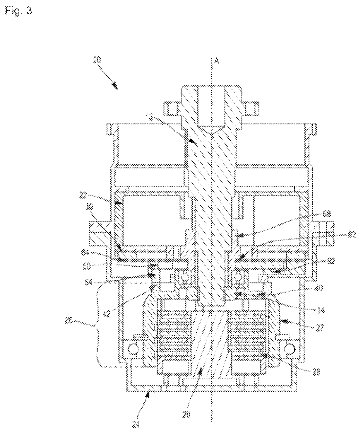
[0061]In a first embodiment, the actuator 30 can be entirely made from the magnetic material. As one variant, only part of the actuator 30 is made of such a material.

[0062]In one exemplary embodiment, the actuator 30 comprises an annular rim 32 made from the magnetic material. By magnetic material, it will be meant here a metal material reacting to the magnetic field generated by the electromagnet 22 so that the electric current supply moves the actuator 30. For example, the actuator 30 can be made of soft iron. A series of through orifices 34 are formed in the rim 32 of the actuator 30 in order to allow its fastening in particular on the fastening part 60, and optionally on the output mesh 50.

Output Mesh 50 of the Coupling Device 40, 50

[0063]The output mesh 50 may comprise an annular crown 52 made from a material strong enough to transmit coupling forces capable of blocking in rotation the shaft 13 of the motor. For example, the output mesh 50 can be made of 15-5 PH stainless steel...

second embodiment

[0069]In a second embodiment, the splines 68 (or the grooves, respectively) are formed directly in the inner face of the central ring 62, the central ring 62 then being directly fastened on the shaft 13 by matching its splines 68 (or its grooves, respectively) with the grooves (respectively the splines 68) of the shaft 13.

[0070]The radial portion 64 of the fastening part 60 comprises a substantially annular periphery 65 which is linked to the central ring 62 by means of a series of tabs 66 so as to make them secured to each other. The diameter of the central ring 62 is smaller than the diameter of the periphery 65 so that the ring lies within the periphery 65. In one embodiment, the periphery 65 is discontinuous and formed of several ring segments, each ring segment being connected to the central ring 62 by means of a tab 66. Each tab 66 may furthermore be curved, as illustrated in FIG. 4.

[0071]The assembly formed by the central ring 62, the periphery 65 and the tabs 66 then constit...


PUM


Abstract

The invention relates to a force application device for an aircraft control stick comprising: —a casing (24), —an electromagnet (22) mounted on the casing (24), —an actuator (30) mounted on the shaft (13), the actuator (30) being mobile in translation in relation to the shaft (13) along the axis (A), the actuator (30) comprising a magnetic material, and —a coupling device comprising an input gear (40) that is mounted so as to be stationary in relation to the casing (24) and an output gear (50) connected to the actuator (30) by means of an attachment part (60), the attachment part (60) being configured so as to allow a limited angular displacement between the output gear (50) and the shaft (13) around the axis (A) and to allow the actuator (30) of the output gear (50) to translate along the axis (A).

Description

CROSS-REFERENCE TO RELATED APPLICATIONS[0001]This application is a National Stage of International Application No. PCT / FR2019 / 053272 filed Dec. 20, 2019, which claims priority under U.S.C. § 119(a) to French Patent Application No. 1873904 filed on Dec. 21, 2018, the entire contents of each of which being herein incorporated by reference in their entireties.FIELD OF THE INVENTION[0002]The invention relates to piloting devices used by the pilot in an aircraft cockpit, in particular an active stick comprising an integrated force feedback to assist the pilot.TECHNOLOGICAL BACKGROUND[0003]A piloting device in an aircraft cockpit comprises, in the usual way, a pilot stick with in particular a lever rotatably mounted about an axis called roll axis and an axis called pitch axis, these two axes being orthogonal to each other. Devices of the “joystick” type are most often encountered.[0004]Depending on the position of the lever along these two axes, the piloting device transmits movement comm...

Claims


Application Information

Patent Timeline
Patent Type & Authority Patents(United States)
IPC IPC(8): B64C13/04G05G5/03G05G9/047B64C27/56
CPCB64C13/0421B64C27/56G05G5/03G05G9/047G05G2505/00
Inventor WERQUIN, MICKAELATTRAZIC, YANNICKLEROUX, CORENTIN
Owner SAFRAN ELECTRONICS & DEFENSE
Why Eureka
Try Eureka