
Illuminated laminate with superior aesthetics and brightness

a technology of automotive glazing and laminates, applied in semiconductor devices, lighting and heating apparatus, instruments, etc., can solve the problems of large glass roofs, unfavorable aesthetics and brightness, and inability or inability to mount a light near the center of the roo

Active Publication Date: 2022-08-23
AGP AMERICA
View PDF7 Cites 0 Cited by
  • Summary
  • Abstract
  • Description
  • Claims
  • Application Information

AI Technical Summary

Benefits of technology

This patent is about a new method for creating a layer in a window that is invisible when the lights are turned off. It uses a special technique to print a pattern on a flat glass layer and then bends it. This pattern is visible when the lights are on, but it is not noticeable when the lights are turned off. The glass layer is made from a special type of glass that has almost no iron, which helps to decrease reflecting light and makes the window brighter. This method improves the brightness and efficiency of the window.

Problems solved by technology

As the cabin volume decreases, it can lead to an unpleasant claustrophobic effect.
A potential problem presented by vehicles with large glass roofs is in the area of cabin lighting.
It is often not possible or not practical to mount a light near the center of the roof.
Indeed, with a lifetime as long as 50,000 hours, the LEDs may well last much longer than the vehicle.
One of the main issues is the high intensity of LEDs intended for general illumination.
Due to the small size of the LED die and the difficulty in including any kind of a lens or diffuser in a laminate, the light intensity of the die tends to be very high.
This can make night driving difficult for the driver.
If the light dispersing layer is visible when the device is in the off state, the substrate can no longer serve also as a window.
These methods tend to produce undesirable haze and also weaken the glass.
A serious drawback to the technology is that the organic matrix is subject to degradation over time with exposure to heat, humidity and UV and it is difficult to apply the emulsion to bent glass shapes as the emulsion must be applied after bending as it would be destroyed by the heat of the glass bending process.

Method used


Image

  • Illuminated laminate with superior aesthetics and brightness
  • Illuminated laminate with superior aesthetics and brightness
  • Illuminated laminate with superior aesthetics and brightness

Examples


example 1

[0074]Outer: 2.3 mm annealed solar green

[0075]Interlayer: 0.76 mm clear PVB

[0076]Inner: 2.3 mm annealed clear

example 2

[0077]Outer: 2.3 mm, press bent coated, clear, annealed, soda-lime glass with ground edge

[0078]Interlayer: 0.76 mm 20% blue PVB

[0079]Inner: 0.7 mm, flat, clear, chemically tempered, aluminosilicate glass with LASER cut edge

[0080]Laminates, in general, are articles comprised of multiple sheets of thin, relative to their length and width, material, with each thin sheet having two oppositely disposed major faces and typically of relatively uniform thickness, which are permanently bonded to one and other across at least one major face of each sheet.

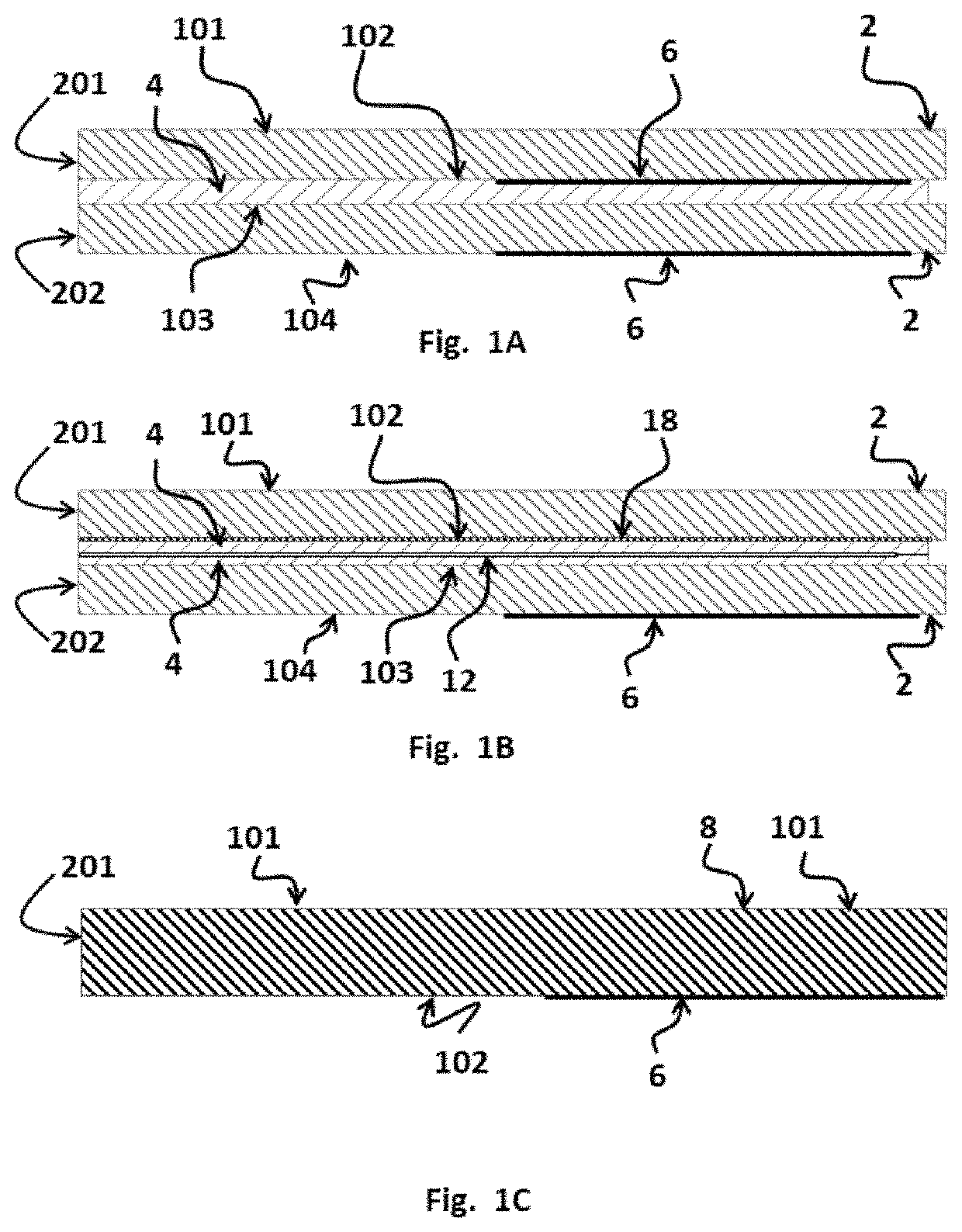
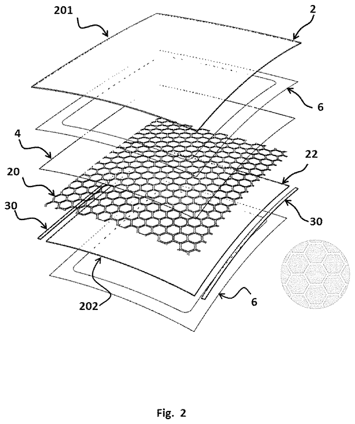
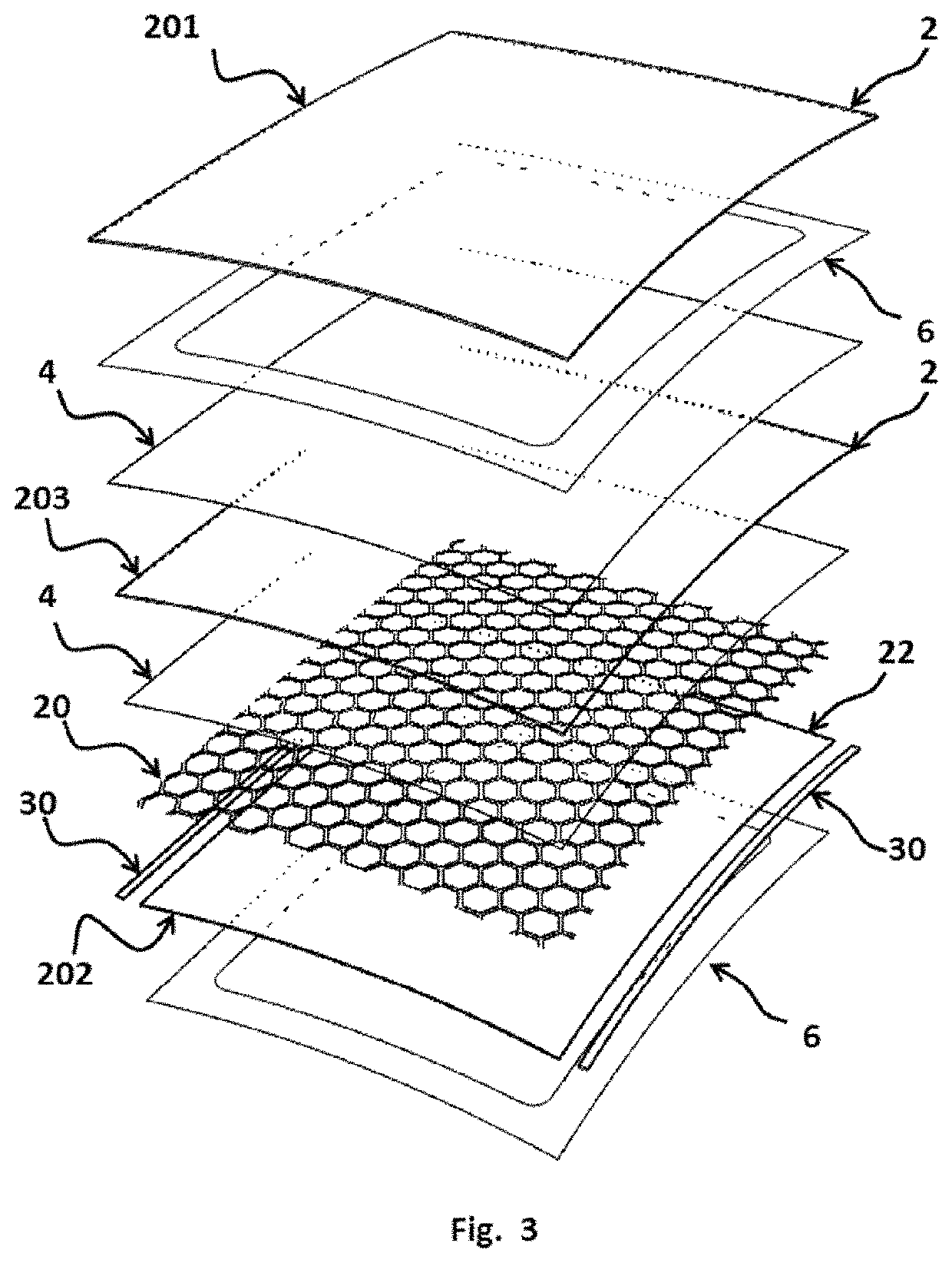
[0081]Laminated safety glass is made by bonding two sheets (201&202) of annealed glass 2 together using a plastic bonding layer comprised of a thin sheet of transparent thermoplastic 4 (interlayer) as shown in FIGS. 1A and 1B.

[0082]Annealed glass is glass that has been slowly cooled from the bending temperature down through the glass transition range. This process relieves any stress left in the glass from the bending process. Annealed glass ...


PUM

PropertyMeasurementUnit
particle sizeaaaaaaaaaa
sizeaaaaaaaaaa
sizeaaaaaaaaaa

Abstract

The trend towards increasing the glazed area in automobiles has reduced the potential locations for mounting cabin lighting. This is especially true for vehicles having large panoramic glazing. Attempts to utilize integrated light sources within the glazing have had mixed results. Embedded LEDs in the laminate tend to be too bright for night driving. Edge feed illumination with light dispersing elements on the glass to date have only been able to provide low intensity levels. Both approaches tend to reduce visibility and aesthetics in the off state. The current invention provides a means and a method to produce a laminate which provides bright cabin lighting without compromising the function of the glazing to serve as a window, by creating a light dispersing layer that is substantially invisible when in the off state and very bright in the on state.

Description

CROSS-REFERENCE TO RELATED APPLICATIONS[0001]The present application claims priority as a continuation-in-part from PCT / IB2020 / 052973 entitled “Illuminated Laminate with Superior Aesthetics and Brightness” filed on Mar. 28, 2020, which claims priority from U.S. Provisional Applications 62 / 826,707, filed on Mar. 29, 2019, and 62 / 846,591, filed on May 10, 2019, all of which are incorporated herein by reference in their entireties.FIELD OF THE INVENTION[0002]The invention relates to the fields of laminated automotive glazing and automotive lighting.BACKGROUND OF THE INVENTION[0003]As automotive manufacturers work to meet government regulations for fuel efficiency and emissions, as well as to provide the type of environmentally friendly vehicles that the public is increasingly demanding, reducing weight has been a key strategy. While substituting lighter weight materials has been a big part of the trend, we have also seen a reduction in the average size of most vehicles. As the cabin vo...

Claims


Application Information

Patent Timeline
Patent Type & Authority Patents(United States)
IPC IPC(8): F21V5/00F21V5/04F21K9/232H01L33/00H01L33/44F21Y115/10
CPCF21V5/04F21K9/232H01L33/005H01L33/44F21Y2115/10B32B17/10036B32B17/10541B32B17/10201B32B17/1022B32B17/10293B32B17/10155B32B17/10348B32B17/10651B32B17/10761B32B17/10889B32B2307/4023B32B2264/10G02B6/0065G02B6/0041B32B17/10119
Inventor MANNHEIM ASTETE, MARIO ARTUROMICHETTI, MASSIMOPENDYALA, RAGHU K.SANTOS, ANDRES FERNANDO SARMIENTOCORNEJO, IVAN ARTUROMENDOZA, GONZALO RAFAEL VIZCARRARAMOS, JORGENUÑEZ-REGUEIRO, JOSÉKRASNOV, ALEXEY
Owner AGP AMERICA
Learn More