Reactor for liquid and gas and method of use

a technology of liquid and gas reactors and reactors, applied in the field of plasma reactors, can solve the problems of requiring higher pressure or alternative expensive methods to increase the amount of oxygen in water, and reducing etc., to achieve the effect of enhancing the gas particle infusion ra

Active Publication Date: 2022-09-27
MILTON ROY
View PDF82 Cites 0 Cited by
  • Summary
  • Abstract
  • Description
  • Claims
  • Application Information

AI Technical Summary

Benefits of technology

[0012]A first embodiment of the current invention provides a plasma laminar flow reactor comprising a housing, an electric field generator, an upper flow spreader, and a lower flow spreader. The housing may include an internal reactor chamber, a gas inlet port, and liquid inlet and liquid outlet ports. The electric field generator may include a first electrode, an optional pre-ionization electrode and a spaced apart second electrode and may generate an electric field or electric fields therebetween. The first electrode and optional pre-ionization electrode may be composed of one or more concentric shapes. A second electrode may have a shape similar to the first electrode or another shape depending on the application and the electrical nature of the liquid passing through the reactor. The second electrode may be spaced close to or spaced farther from the first electrode. In cases where the second electrode is not in close proximity to the first electrode, the second electrode may have any shape convenient to the design. Together, the first and second electrodes may produce a cylindrical electrical field close to the first electrode. The optional pre-ionization electrode may produce an electric field in close proximity to the field produced by the first electrode and second electrode. The plasma laminar flow reactor may also include a dielectric element positioned between the first electrode, the optional pre-ionization electrode, and the second electrode adjacent to the first electrode and optional pre-ionization electrode. The upper flow spreader may supply a stream of gas and liquid to the reactor chamber and may be positioned within the reactor chamber concentrically with the first electrode and the optional pre-ionization electrode. The lower flow spreader may supply a base for the stream of liquid as it flows to the reactor chamber and may be positioned within the reactor chamber concentrically with the first electrode and the upper flow spreader. The gas may create a gas zone inside the reactor chamber. The stream of liquid and the stream of gas may flow adjacent one another radially outward from the center of the reactor chamber and pass through the electric field. This may allow the gas and liquid to create and maintain two layers (gas over liquid) as the gas and liquid pass through the electric field. The gas may be injected from a relatively higher pressure gas source than the liquid through a flow limiting valve, small pump either as a steady flow or pulsed on and off, or other means well known to those familiar with gas control systems, such that the gas zone above the liquid is maintained.
[0013]A second embodiment of the current invention provides for an alteration of the second electrode by adding a dielectric isolation between the second electrode and the liquid. This may enable complete electrical isolation of the drive electronics and the liquid and gases to be used in the reactor. In addition, this may allow for plasma reactors without any conductive elements contacting the liquid.
[0014]A third embodiment of the current invention provides an alteration to the first electrode, the pre-ionization electrode, and / or the second electrode that can be used to modify the electrical characteristics of the reactor. This may enable larger reactors and more flexibility in design. In this embodiment the electrode is broken into several smaller electrodes. This may allow the plasma area to be larger without a proportional increase in the capacitance of the first electrode. This may be desirable for the voltage generator. The number of first or second electrodes may depend on the needs of the reactor and the reaction desired.
[0017]In another aspect of the present invention, a reactor system and method is configured for injecting or infusing ionized molecular particles, ionized monatomic particles, and / or non-ionized particles of a gas into a flowing or non-flowing liquid. The reactor includes a reaction chamber configured for holding a liquid and a gas adjacent to the liquid. A high intensity alternating current (AC) electric field is connected and applied to the reaction chamber, configured for making contact with the gas and / or the liquid. The voltage power level of the AC electric field is configured for adjustment as desired for optimizing desired gas particle injection, infusion, or diffusion into liquid. By varying the electrical field strength of these systems, the ratio of molecular infusion and ionic injection can be controlled. In embodiments of the present invention, the AC electric field may or may not ionize molecules in a gas or liquid and may terminate in a liquid. Moreover, the electric field may pass through a gas to be infused into a liquid while the gas is adjacent to the liquid and / or pass through the liquid. The present invention is configured for adjustment of the electric field to enhance the infusion of gas particles into liquid.

Problems solved by technology

This type of diffusion can be enhanced but requires using higher pressure or alternative expensive methods to increase the amount of oxygen in the water.
However, each of these oxygen diffusion methods suffer from loss of significant amounts of oxygen, poor diffusion, and / or substantial monetary costs.
Similarly, other systems that attempt to diffuse gas into liquids suffer from low diffusion rates, and saturation using traditional means is limited.

Method used


Image

  • Reactor for liquid and gas and method of use
  • Reactor for liquid and gas and method of use
  • Reactor for liquid and gas and method of use

Examples


first embodiment

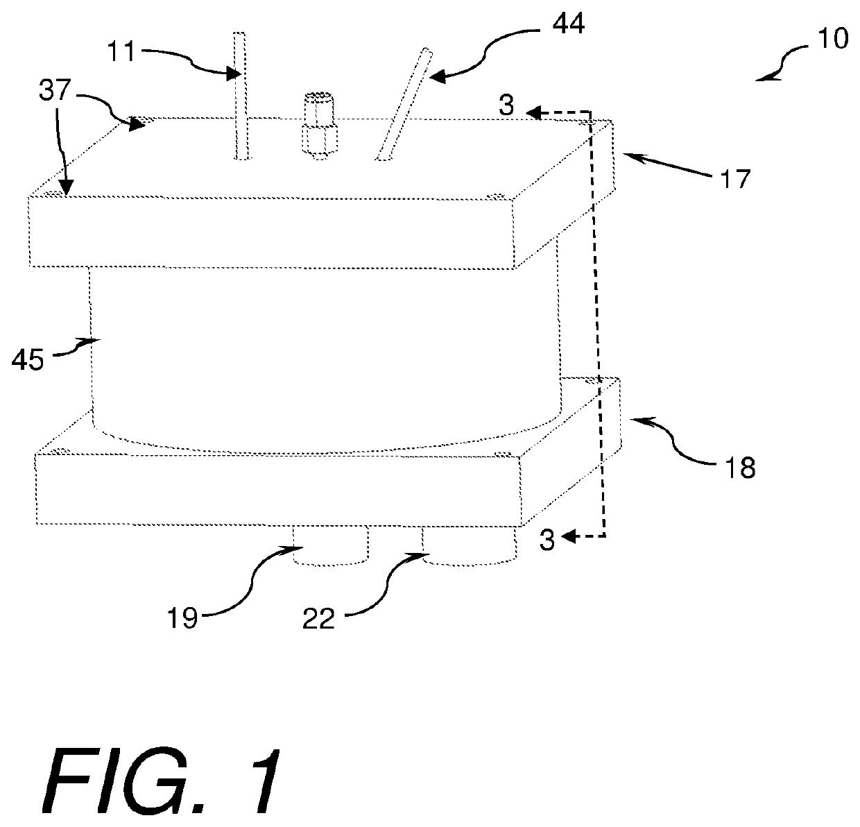
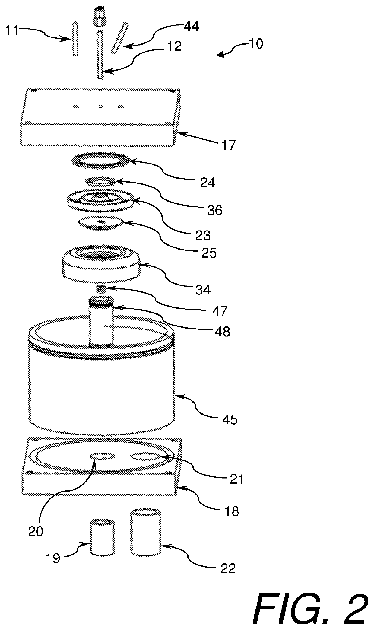
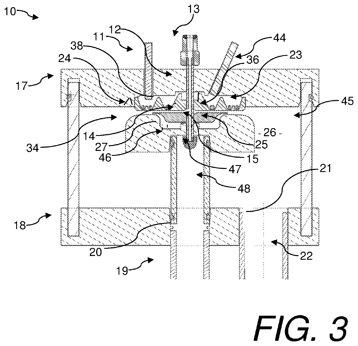
[0041]Referring to FIGS. 1-5, a plasma reactor 10, constructed in accordance with at least the current invention, is shown. The reactor 10 generally receives a gas, a liquid, and electrical stimulus as inputs. The gas may be ionized to form a plasma over the liquid which is in contact with the liquid. The ionized gas interacts with the liquid to create an effluent or product. The plasma reactor 10 broadly comprises a lower housing 18, a housing wall 45, an upper housing 17, at least one dielectric element 23, an upper flow spreader 25, a lower flow spreader 34, first electrode(s) 24, a second electrode which may be the lower flow spreader 34 or another second electrode configuration herein described, and a reaction or effluent chamber 26. The reactor may also include an optional pre-ionization electrode 36. An electric field generator may be attached to the first and second electrodes. In cases where an optional pre-ionization electrode is utilized, an electric field generator may b...

second embodiment

[0061]Referring to FIG. 6, the reactor utilizes a dielectrically isolated second electrode 29. In some applications which may include oxygen and ultra-high purity water, it may be desirable to avoid any liquid contact with metallic elements or elements that are conducting electricity. Other applications where this is desirable may include applications where the liquid is not able to be connected to an electrical potential. There are other applications that may benefit from a dielectric isolation not listed here. In these applications the second electrode may be dielectrically isolated from the liquid by using a second electrode 29. This electrode may be placed in the lower flow spreader 34 and covered with a material such as ceramic, polymer, or other materials known by those familiar with the art to isolate the alternate electrode 29 from the liquid stream. In these cases the electrical field will be shared by the dielectric element 23, the gas flow below the dielectric element, th...

third embodiment

[0062]Referring to FIG. 7, this reactor may split the first electrode into several alternate first electrodes 41. These alternate first electrodes 41 may be annular or other shapes, may be located in the internal cavity 38, and may be isolated from the reactor chamber 26 by the dielectric element 23. In addition, this type of electrode may be used for alternate optional pre-ionization electrodes 49. By using multiple electrodes, the electrical characteristic of a reactor of a given size may be altered thereby enabling a greater plasma area without a corresponding increase in electrode capacitance and simplifying the design of the electrical source to drive the electric field required to generate a plasma. One or more first electrodes may be used in a given reactor. One or more optional pre-ionization electrodes may be used in a reactor. The use of a type of one or more first electrodes in a given reactor may depend on the reactor size, type of reaction desired, and / or other consider...


PUM

PropertyMeasurementUnit
Oxidation Reduction Potentialaaaaaaaaaa
voltageaaaaaaaaaa
pressureaaaaaaaaaa

Abstract

A system and method for performing plasma reactions creating a plasma area in a gas adjacent to a liquid. An embodiment of the plasma reactor includes a housing with an internal reaction chamber, first and second inlet paths to the reaction chamber, and electrodes for producing an electric field. The system may optionally further include a pre-ionization electrode and pre-ionization electric field for pre-ionizing a feed gas prior to entry into a reaction chamber. The reactor uses plasma to ionize gas adjacent with the liquid. The ionized gas reacts with the liquid to form an effluent. Exemplary uses of the plasma reactor include ionic injection, gas dissociation, liquid re-formation, and liquid dissociation. An alternative embodiment provides a system and method for infusion of gaseous particles into liquid by applying an electric field at power levels lower than the voltage required to form a plasma to gas adjacent to liquid.

Description

CROSS-REFERENCE TO RELATED APPLICATIONS[0001]This application is a continuation-in-part of and claims priority in U.S. patent application Ser. No. 16 / 027,005, filed Jul. 3, 2018, which is a continuation-in-part of U.S. patent application Ser. No. 15 / 277,093, filed Sep. 27, 2016, now U.S. Pat. No. 10,010,854, which claims priority in U.S. Provisional Patent Application Ser. No. 62 / 235,750, filed Oct. 1, 2015. The contents of the aforementioned applications are incorporated by reference herein in their entireties.BACKGROUND OF THE INVENTION1. Field of the Invention[0002]Embodiments of the current invention relate to plasma reactors and methods and systems that utilize plasma reactors.2. Description of the Related Art[0003]Plasma reactors may include at least two electrodes which are spaced apart. Typically, a voltage difference is applied to the electrodes and an electric field is established between them. A stream of gas may be introduced to the space between the electrodes such that...

Claims


Application Information

Patent Timeline
Patent Type & Authority Patents(United States)
IPC IPC(8): B01J19/08C01B13/02B01J4/00C01B13/10C01B15/01
CPCB01J19/088B01J4/001B01J4/002C01B13/02C01B13/10C01B15/01B01J2219/0809B01J2219/0869B01J2219/0884B01J2219/0896
Inventor BUCHANAN, WALTER RILEYFORSEE, GRANT WILLIAM
Owner MILTON ROY
Why Eureka
Try Eureka