Flat heat element for microvaporizer

a heat element and micro-vaporizer technology, applied in ohmic-resistance heating, tobacco, electrical equipment, etc., can solve the problem that conventional coiled heating wires are incapable of utilizing multi-zone heating

Active Publication Date: 2022-10-04
PHILLIPS DONOVAN +1
View PDF14 Cites 1 Cited by
  • Summary
  • Abstract
  • Description
  • Claims
  • Application Information

AI Technical Summary

Benefits of technology

[0006]The conventional coiled heating wire is incapable of utilizing multi-zone heating, and must vary the magnitude of electrical power applied to the coil in order to regulate the temperature of the liquid flowing through the microvaporizer. The single-zone configuration has less control over the temperature of the liquid in the microvaporizer and allows for greater fluctuations in temperature, which in turn leads to greater fluctuations in particle size within the aerosol.
[0007]The flat heater described herein attempts to improve the deficiencies of the conventional design. For example, the flat heater is a simpler design that uses less material and can regulate the amount of heat applied to the liquid. Because the flat heater can control the amount heat applied to the liquid, the flat heater can control the size of particles in the aerosol and can even produce different predetermined particle sizes within an aerosol mixture. For example, for nicotine absorption smaller vapor dimensions (particle size) allow nicotine to flow deep into the lung. At the same time, larger particle dimensions are better at activating taste buds on the tongue. Unlike conventional microvaporizer heaters, the flat heater described herein can generate both particle sizes with consistency.
[0008]In addition, because the flat heater can regulate the amount of heat, the flat heater can avoid reaching temperatures that produce certain carcinogens.

Problems solved by technology

The conventional coiled heating wire is incapable of utilizing multi-zone heating, and must vary the magnitude of electrical power applied to the coil in order to regulate the temperature of the liquid flowing through the microvaporizer.

Method used


Image

  • Flat heat element for microvaporizer
  • Flat heat element for microvaporizer
  • Flat heat element for microvaporizer

Examples


Embodiment Construction

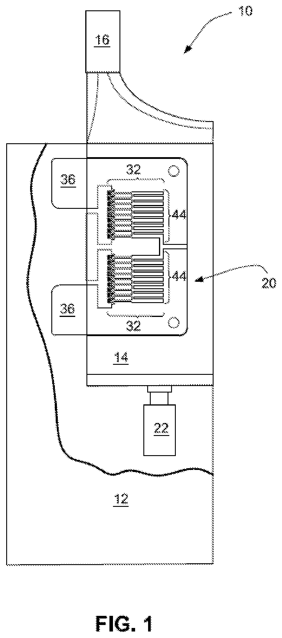
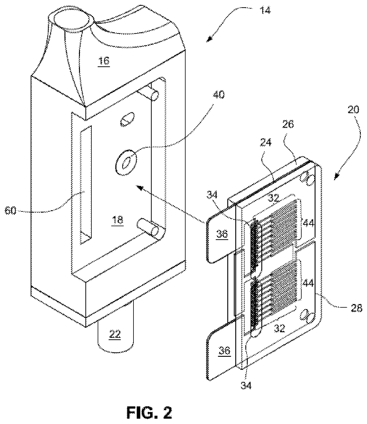
[0063]FIG. 1 shows an exemplary microvaporizing device 10 for generating an aerosol for inhalation by a user. The microvaporizing device 10 may include a base 12 and a cartridge 14. The base 12, may be configured to receive one of a plurality of interchangeable cartridges 14 and may house a power source, such as a battery and / or electronics. The cartridge 14 may include a mouthpiece 16 for delivering the aerosol directly to the user's mouth and may include a mount (e.g., recess 18—see FIG. 2) for a heater 20. The power supply may provide electrical power to the heater 20 and the electronics may control the electrical energy supplied the heater 20. In addition, a storage tank or reservoir for fluid to be vaporized may be housed in the base 12 and / or in the cartridge 14. The cartridge 14 may also include a pump 22 to pump the fluid from the reservoir through the cartridge 14. The cartridge 14 may be permanently attached to the base 12 or releasably attached to the base 12.

[0064]As sho...


PUM


Abstract

A heater assembly (20) is configured to vaporize a liquid. The heater assembly (20) includes a substrate plate (26,28) and a heating element (24) supported on the substrate plate (26,28). The heating element (24) includes a layer of electrically conducting material. The heater assembly (20) further includes a plurality of channels (46) formed by the electrically conducting material. Each of the plurality of channels (46) is configured to operate in parallel. Each channel (46) has an inlet end and an outlet end. The inlet end is configured to receive the liquid and the outlet end is configured to discharge vapor. The substrate plate (26,28) and the heating element (24) form a multi-layer configuration.

Description

[0001]This application is the U.S. national phase of International Application No. PCT / CN2019 / 085707 filed May 6, 2019 which designated the U.S., the entire contents of each of which are hereby incorporated by reference.(1) FIELD OF THE INVENTION[0002]The invention relates to a heater for microvaporizer, and particularly to an electrically heated element incorporated into a cartridge for the microvaporizer.(2) DESCRIPTION OF RELATED ART[0003]Microvaporizers, also referred to as vaping devices, provide alternatives to cigarettes, cigars, pipes and other tobacco smoking devices. Vaping devices may be configured to provide the sensations associated with cigarette, cigar, or pipe smoking, but without delivering considerable quantities of incomplete combustion and pyrolysis products that result from the burning of tobacco. Microvaporizers may also be configured to deliver medicinal aerosols, such as asthma breathers.[0004]Conventional microvaporizer heaters typically include a coiled hea...

Claims


Application Information

Patent Timeline
Patent Type & Authority Patents(United States)
IPC IPC(8): A24F40/46A24F40/48A24F40/10A24F40/44A24F40/57A24F40/42H05B1/02H05B3/26
CPCA24F40/46A24F40/10A24F40/42A24F40/44A24F40/48A24F40/57H05B1/0244H05B3/26H05B2203/005H05B2203/021H05B2203/037
Inventor XIE, HAOJUN
Owner PHILLIPS DONOVAN
Why Eureka
Try Eureka