Gradient sensor

a gradient sensor and sensor technology, applied in the field of differential gradient measurement systems and methods, to achieve the effect of convenient configuration of gradient measuremen

Active Publication Date: 2022-11-08
WOODS HOLE OCEANOGRAPHIC INSTITUTION
View PDF15 Cites 1 Cited by
  • Summary
  • Abstract
  • Description
  • Claims
  • Application Information

AI Technical Summary

Benefits of technology

[0011]An object of the present invention is to provide an improved gradient sensing device which is more readily configurable to measure gradients of one or more selected modalities.
[0012]Another object of the invention is to provide more cost-effective, more accurate and / or higher-resolution gradient measurements in real time.

Problems solved by technology

Existing underwater gradient measurement systems are capable of collecting and recording marine physical gradients, however most designs have not changed in many years and these systems are imprecise, difficult to build devices with low resolution of gradient sensing.
Sensor data is then stored onboard the device, with limited data relay capabilities and no real-time, operational control of the deployed device.
However, existing heat flow probe technology suffers from 1) inadequate gradient sensing resolution, 2) handling and transport difficulties due to size and weight, 3) insufficient real-time data communication transfer capabilities, 4) imprecise position and orientation sensing, and 5) inappropriate probe design (e.g. length) for changing target mediums in an area of interest.
HFPs of the art are limited by the number of sensors they can incorporate into their design.
This drawback physically limits the resolution and data accuracy by limiting the number of sensors, typically to less than about 10 sensors, and introduces significant thermal mass issues which may alter readings.
Running analog sensor output wires from the bow string sensor to the housing also increases the complexity of the connections between these components.
Complex electrical connections introduce signal noise between the sensors, reducing the data limits of detection, resolution and accuracy.
Complex connections also prevent the probes from being modular; in other words, users cannot easily swap different probe components during an exploratory cruise.
Another limitation of HFPs is that they generally contain only crude acoustic output capability via simple a pingers.
Therefore, current HFPs are generally limited to pre-programmed operational parameters, including heat pulse duration, delay and intensity that cannot be adjusted in real time during probe operation.
Existing gradient sensing systems are also limited in other parameters they can measure and the amount of associated information that can be sent back to the user in real time.
Furthermore, many conventional systems do not have the bandwidth to send tilt, sensor or battery life information back to the user in real-time.
Current HFPs have are limited in use, because they lack significant modularity of their consistent components.
For example, only a subset of current HFPs contain removable bow string sensing segments, a necessary requirement to effect repairs while in the field, because probes routinely get bent or broken on insertion of the target medium.
Calibration must be performed in highly controlled laboratory conditions and involve a large water bath stepped heating test, which is not possible to perform at sea and get meaningful data for proper calibration.
Currently, HFPs lack easy removability of their controller, logger or battery components.

Method used


Image

  • Gradient sensor
  • Gradient sensor
  • Gradient sensor

Examples


Embodiment Construction

Overview

[0049]The systems and methods described herein will now be described in detail with references to illustrative embodiments. The described features, advantages, and characteristics of the invention may be combined in any suitable combination in one or more embodiments. One skilled in the relevant art will be aware that the present invention may be practiced with or without one or more of the specified features or advances present in a particular embodiment. In some cases, features and advantages may be present in some embodiments that are not present in others. These illustrated embodiments are for the purpose of describing the inventive system and methodologies and are not to be understood to be limiting in any way.

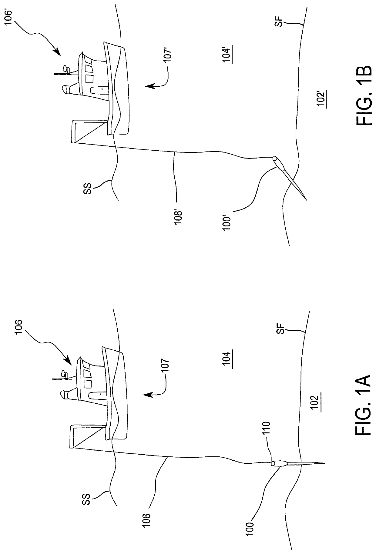
[0050]In some constructions according to the instant invention, the Gradient Sensing Device functions as a Heat Flow Probe (“HFP”) for measuring thermal conductivity of sediments and other soft, penetrable solids. Like previous HFPs, in operation, it is plunged in...


PUM

PropertyMeasurementUnit
lengthaaaaaaaaaa
temperaturesaaaaaaaaaa
tilt angleaaaaaaaaaa

Abstract

A gradient sensing probe system, and method of using same, including a sensing segment which includes a plurality of sensors, a support structure, and an electrical interface having first and second faces. The system further includes a housing, a power source, and an electronics package including a controller and disposed within the housing. The sensing segment is configured to measure external gradients and to exchange data with the controller. The power source is connected energetically to provide power to the sensing segment and the electronics package, and is controlled by the controller.

Description

CROSS REFERENCE TO RELATED APPLICATIONS[0001]This application claims priority to U.S. Provisional Application No. 62 / 537,113 filed on Jul. 26, 2017, the contents of which are hereby incorporated as if set forth herein in its entirety.FIELD OF THE INVENTION[0002]This invention relates to systems and methods for measuring differential gradients in target media, and more particularly to a probe system for measuring gradients (e.g. thermal) or other physical properties of marine sediments.BACKGROUND[0003]The precise measurement of physical and chemical gradients in fluid and marine environments is a requirement for many oceanographic pursuits. Understanding magnetic, thermal, acid, and vibrational gradients in underwater environments has importance in both basic research and in applied areas such as oil, gas and ore exploration and development. Gradient measurements contribute to our knowledge of the composition of sea floor sediments, subduction zones, marine sea mounts and ridges.[000...

Claims


Application Information

Patent Timeline
Patent Type & Authority Patents(United States)
IPC IPC(8): G01K17/08G01C9/02G01K1/02G01K13/00G01C13/00
CPCG01K17/08G01C9/02G01C13/00G01K1/026G01K13/00G01K2215/00
Inventor SANGER, RICHARDFUCILE, PAUL D.TIVEY, MAURICE
Owner WOODS HOLE OCEANOGRAPHIC INSTITUTION
Why Eureka
Try Eureka