Selective catalytic reduction catalyst pre-heating and exhaust burner air control

a catalytic reduction catalyst and preheating technology, applied in the direction of electrical control, machine/engine, exhaust treatment electric control, etc., can solve the problems of inability to react with nox at elevated exhaust temperatures, and inability to achieve high nox levels in vehicles

Active Publication Date: 2022-11-22
TENNECO AUTOMOTIVE OPERATING CO INC
View PDF26 Cites 3 Cited by
  • Summary
  • Abstract
  • Description
  • Claims
  • Application Information

AI Technical Summary

Problems solved by technology

The SCR catalyst may only be effective at reacting with NOx at elevated exhaust temperatures.
Exhaust tempe...

Method used


Image

  • Selective catalytic reduction catalyst pre-heating and exhaust burner air control
  • Selective catalytic reduction catalyst pre-heating and exhaust burner air control
  • Selective catalytic reduction catalyst pre-heating and exhaust burner air control

Examples


Embodiment Construction

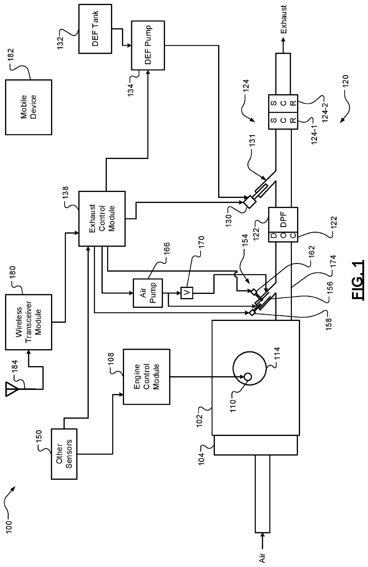
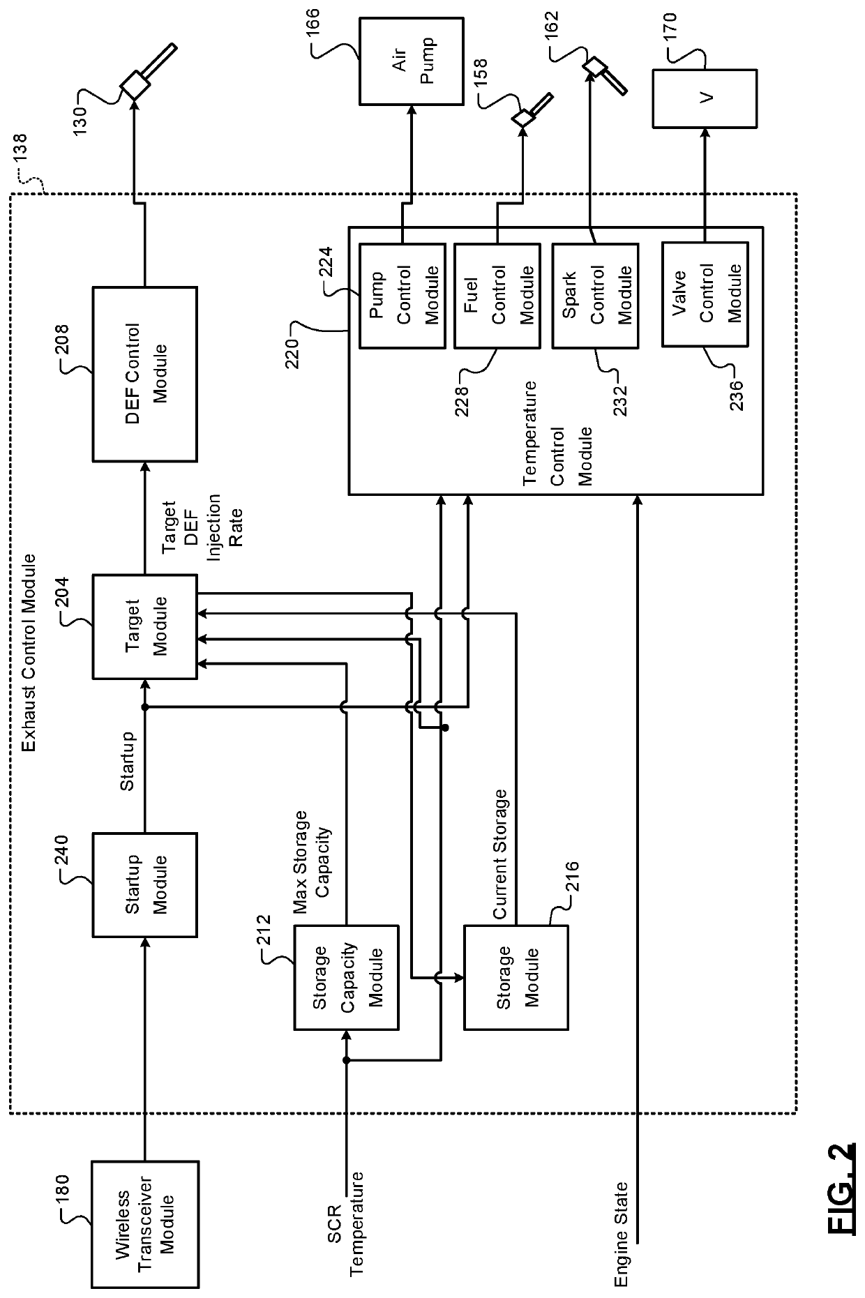
[0036]A control module controls injection of a diesel exhaust fluid (DEF) into an exhaust system upstream of a selective catalytic reduction (SCR) catalyst. The SCR catalyst receives exhaust output by an engine of a vehicle. The exhaust includes nitrogen oxides (NOx). The DEF includes urea and water. Heat from the exhaust decomposes urea from the DEF into ammonia (NH3). The SCR catalyst stores ammonia. Ammonia reacts with NOx in the exhaust thereby reducing the amount of NOx that is output from the SCR catalyst.

[0037]The engine may generate a high level of NOx at startup. The amount of ammonia stored on (by) the SCR at startup, however, may be low. The temperature of the exhaust at engine start up may be too low to enable DEF injected into a decomposition tube to be processed into ammonia. The NOx output of the vehicle may therefore be relatively high after engine startup.

[0038]The present application involves warming the SCR catalyst using a burner before engine startup, such as wh...


PUM


Abstract

An exhaust control system of a vehicle includes a fuel injector configured to inject fuel into a combustion chamber of a burner of an exhaust system upstream of a selective catalytic reduction (SCR) catalyst; an air pump configured to pump air into the combustion chamber of the burner; a spark plug configured to ignite an air/fuel mixture within the combustion chamber of the burner; a fuel control module configured to, while an engine is off before an engine startup, selectively actuate the fuel injector and begin fuel injection; a pump control module configured to, while the engine is off before the engine startup, selectively turn on the air pump; and a spark control module configured to, while the engine is off and before the engine startup, selectively apply power to the spark plug and begin providing spark.

Description

FIELD[0001]The present disclosure relates to exhaust control systems and methods and more particularly to systems and methods for controlling selective reduction catalyst (SCR) temperature and airflow into an exhaust system.INTRODUCTION[0002]The information provided in this section is for the purpose of generally presenting the context of the disclosure. Work of the presently named inventors, to the extent it is described in this section, as well as aspects of the description that may not otherwise qualify as prior art at the time of filing, are neither expressly nor impliedly admitted as prior art against the present disclosure.[0003]Air is drawn into an engine through an intake manifold. The air mixes with fuel from one or more fuel injectors to form an air / fuel mixture. The air / fuel mixture is combusted within one or more cylinders of the engine. Combustion of the air / fuel mixture generates torque.[0004]Exhaust resulting from the combustion of the air / fuel mixture is expelled fro...

Claims


Application Information

Patent Timeline
IPC IPC(8): F02D41/02F01N3/20F02D41/06F01N3/32
CPCF02D41/024F01N3/2033F01N3/2066F01N3/32F02D41/062F01N2610/11Y02T10/12Y02A50/20F01N3/22F01N9/00F01N2610/03F01N2610/085F01N2900/1806F01N2900/1804F01N2900/08F01N2610/144F01N2610/146F01N2900/10F01N2610/02
Inventor HARRIS, THOMAS M.MUHLECK, MATTHEW
Owner TENNECO AUTOMOTIVE OPERATING CO INC
Why Eureka
Try Eureka