Milling method

a technology of workpieces and milling methods, applied in the direction of program control, instruments, total factory control, etc., can solve the problems of loss of synchronicity between path parameters and spindle position, uneven surface appearance (wider stripes), etc., and achieve the effect of improving surface quality

Active Publication Date: 2022-11-22
EXERON
View PDF5 Cites 13 Cited by
  • Summary
  • Abstract
  • Description
  • Claims
  • Application Information

AI Technical Summary

Benefits of technology

[0008]An objective of the present invention is to provide a method which makes it possible to produce a phasing of the tool cutting edge interactions in adjacent toolpaths in a targeted manner. In particular, an objective is to improve the surface quality.Technical Solution
[0014]In embodiments of the present invention, the phase position may be controlled by reducing or increasing the spindle speed. Thus, without changing the feed rate, the phase position of the spindle can be controlled by regulating the spindle speed alone.

Problems solved by technology

At constant spindle speed, this means that the synchronicity between path parameters and spindle position is lost.
Sometimes, however, shifts occur, which then lead to an optically uneven appearance (wider stripes) of the surface.

Method used


Image

  • Milling method
  • Milling method
  • Milling method

Examples


Embodiment Construction

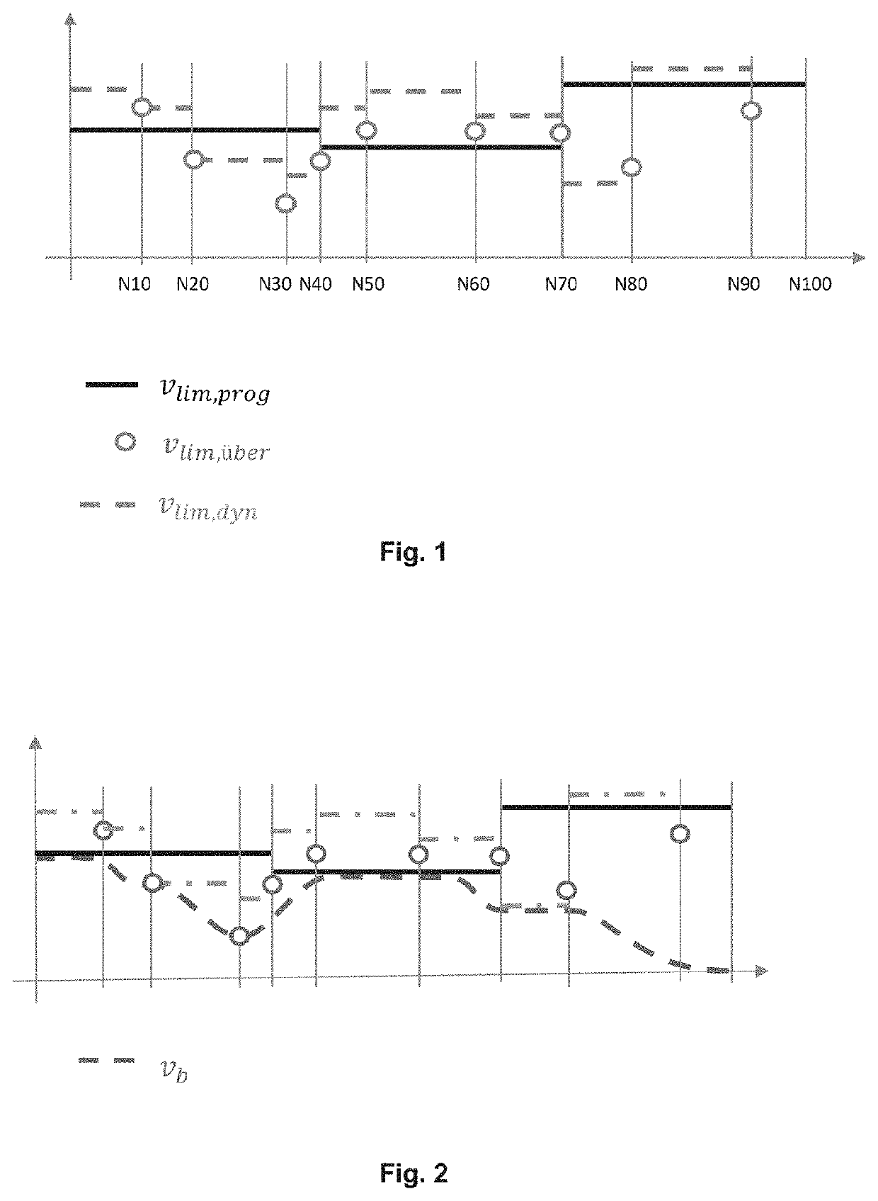
[0029]NC (numerical control) programs describe the milling path in a sequence of simple geometric elements. Support points or path support points are the respective boundaries between two subsequent geometry elements. These coordinates are taken from the NC program per line as NC block. The path parameter (also called path length integral) describes exactly one point on the path described in the part program, which may well lie between the support points of the NC blocks

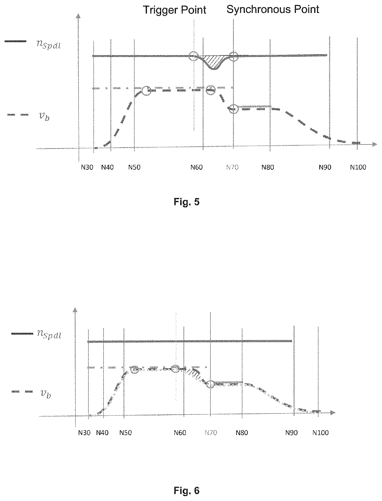
[0030]In the following, a synchronous point is understood to be any point of the path (=path parameter) at which simultaneously applies:

[0031]nSpdl=nprog (the spindle speed is at the value specified in the program)

[0032]νb=νprog (the feed rate is at the value specified in the program)

[0033]φSpdl=φprog (the angular position (phase) of the spindle is at the value specified in the program)

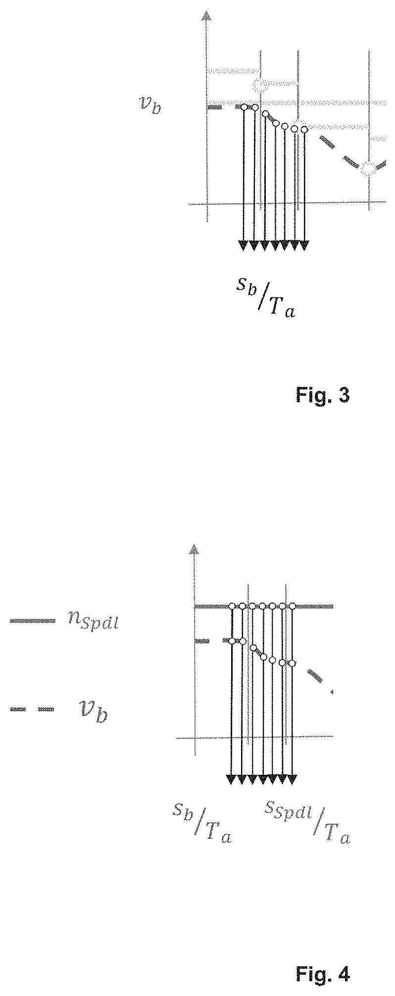
[0034]aSpdl=0 (the spindle speed is constant)

[0035]ab=0 (the spindle is not accelerated in x, y, z direction)

[0036]A trigger point is...


PUM


Abstract

The invention relates to a method for machining a workpiece by means of a milling tool arranged on a rotatable spindle, the spindle being moved relative to the workpiece or the workpiece being moved relative to the spindle along a machining path and, at the same time, the spindle rotating about a spindle axis. In said method, an improvement in the surface quality is achieved by controlling the rotational speed and / or the phase position of the rotation of the spindle along the machining path, the machining path comprising linear parallel tracks and the phase position of the spindle along the machining path being substantially the same on adjacent tracks, the phase position being controlled by varying the rotational speed of the spindle and / or the advancing speed of the spindle relative to the workpiece along the machining path.

Description

CROSS REFERENCE TO RELATED APPLICATIONS[0001]This application is a U.S. National Phase Application of PCT International Application No. PCT / EP2019 / 067869, filed Jul. 3, 2019, which claims benefit of priority from German Patent Application No. 10 2018 116 553.6, filed Jul. 9, 2018. The contents of these applications are incorporated herein by reference.TECHNICAL FIELD[0002]The present invention relates to a method for machining a workpiece with a milling tool arranged on a rotatable spindle, wherein the spindle is moved relative to the workpiece or the workpiece is moved relative to the spindle along a machining path and the spindle rotates about a spindle axis, wherein a rotational speed and / or a phase position of the rotation of the spindle along the machining path is controlled, as well as a device and a computer program for carrying out the method and a data structure for coding the computer program.BACKGROUND ART[0003]In modern machine tools, numerical controls are used to contr...

Claims


Application Information

Patent Timeline
Patent Type & Authority Patents(United States)
IPC IPC(8): G05B19/4093B23C3/00
CPCG05B19/40937B23C3/00G05B2219/34175G05B2219/49077Y02P90/02
Inventor MAYER, JOACHIM
Owner EXERON
Why Eureka
Try Eureka