Electric power generation system for electric vehicles

a technology for electric vehicles and power generation systems, applied in the direction of propulsion parts, gas pressure propulsion mounting, transportation and packaging, etc., can solve the problems of limited range and slower speeds, and achieve the effects of increasing the maximum speed capabilities of electric vehicles, rapid depletion of electricity, and improving efficiency

Inactive Publication Date: 2001-07-19
SMITH VINCENT A +2
View PDF0 Cites 45 Cited by
  • Summary
  • Abstract
  • Description
  • Claims
  • Application Information

AI Technical Summary

Problems solved by technology

This finite amount of energy storage is the major drawback for EV s, resulting in limited range and slower speeds, especially in comparison with gasoline-powered vehicles.

Method used


Image

  • Electric power generation system for electric vehicles
  • Electric power generation system for electric vehicles
  • Electric power generation system for electric vehicles

Examples


Embodiment Construction

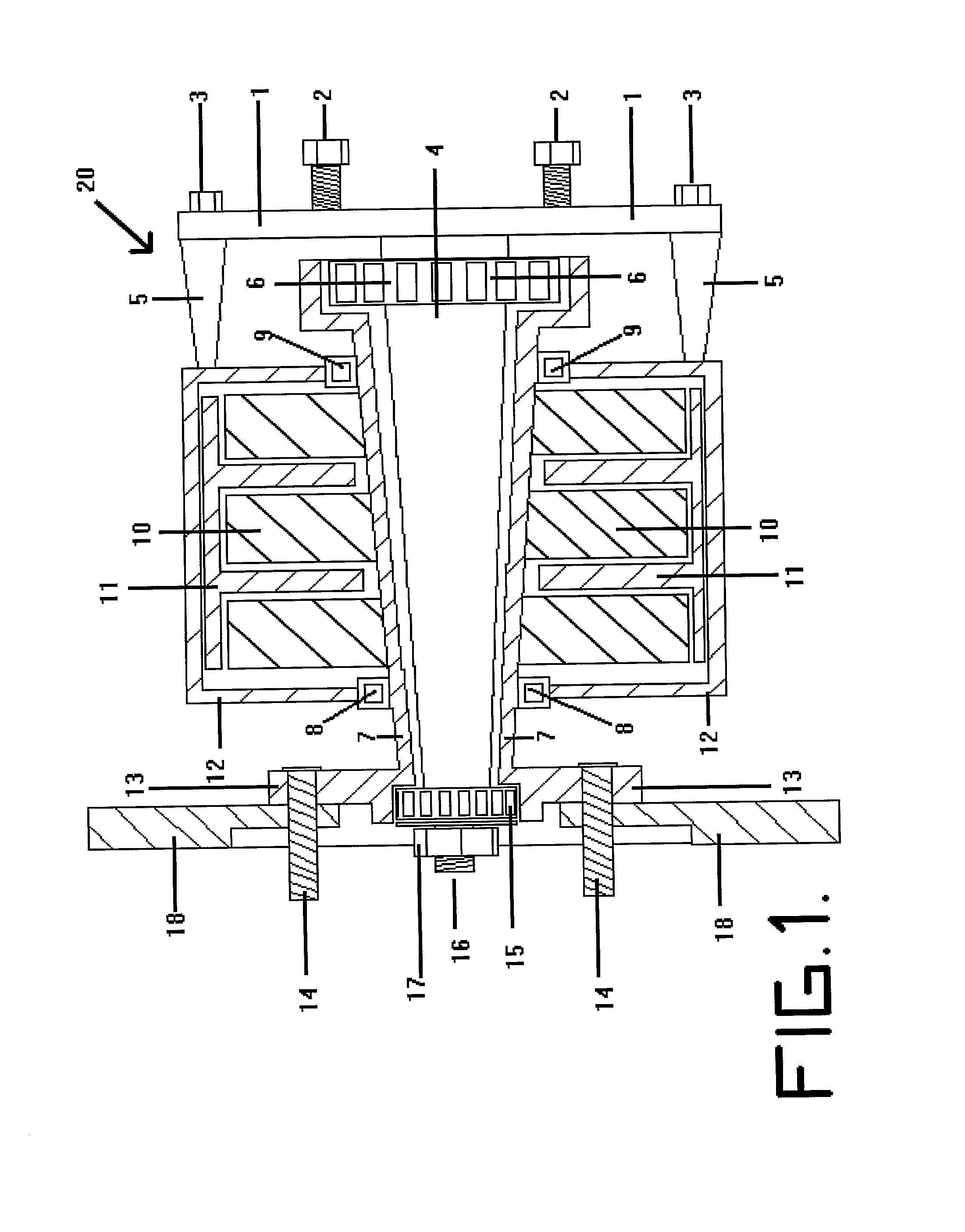
[0044] FIG. 1 is a section taken along an axle of common vehicle illustrating a first embodiment of the invention, viz., a permanent magnet, brush-less alternator / generator version; Regenerator 20. The backing plate / mounting plate 1 is bolted to a vehicle frame via a suspension (both not shown) and mounting bolts 2. The spindle 4 of the wheel bearing assembly is integrated with the mounting plate 1. The spindle 4 has two bearing assemblies 6 and 15 that support and allow the hollow cylindrical rotor 7 to rotate around the spindle 4. The distal end of the spindle 16, distal to the vehicle frame, has been necked down and threaded to allow attachment of a bearing assembly 15, and retaining nut 17. The rotor 7 has permanent magnets 10 attached to it for generating a rotating magnetic field. The rotor 7 has a mounting plate 13 that allows the placement of lug bolts 14, to which a vehicle's tires may be mounted. There is a disk 18 of a disk brake assembly that fits over the lug bolts 14,...


PUM


Abstract

An electrical power generating system is described for generating electrical energy for an electric vehicle, via the motion of the non-drive wheels, which converts kinetic energy to electrical energy to replenish the batteries of said vehicle. The preferred version places one or more alternator / generator(s) at the non-driven wheels of the vehicle. Each alternator / generator is unitarily formed with respect to a mounting plate unitarily formed with respect to said mounting plate and said vehicle's suspension, and each alternator / generator includes a rotating field means integrated with the rotating mounting plate attached to the wheel and a stationary stator means stationarily attached to the frame through the suspension. Conventional electrical contact means attached to between said rotating field means and said stationary stator means for generating electrical current for said vehicle. Since the mechanical loading on the spindle bearing assemblies has been substantially increased, the bearing assemblies of the invention are of a heavy-duty design. That is, such bearing assemblies are large enough to handle the weight of said vehicle, including that of the alternator, as well as the weight of the wheel assembly, including tire and brakes. As the vehicle moves forward or backward, the rotational force applied to the vehicle's wheels will rotate the integrated rotating field means relative to the stationary stator means to produce alternating current (AC). Alternating current is converted to direct current (DC) either by a diode bridge, transformer, or controller, for distribution to the EV's electrical system. DC electricity is used to recharge storage batteries, provide electricity for the drive motor and operate the vehicle's electrical equipment. Thus, the regenerative system, does not add any additional load on the drive motor. Wheel bearing assemblies are usually used for all wheels on vehicles and the very nature of bearing assemblies are to reduce friction. By the incorporation of alternators into the wheel bearing assemblies, a vehicle can generate electricity when moving, without additional workload to the drive train; since wheel bearing assemblies are a necessary and integral part of any rolling vehicle and by their very nature reduce friction and resistance.

Description

[0001] This is a continuation-in-part of Ser. No. 60 / 176,934 filed Jan. 18, 2000 for "IN-LINE ELECTRIC POWER GENERATING SYSTEM FOR AN ELECTRIC VEHICLE" by Vincent A. Smith and Susan V. Smith.SCOPE OF THE INVENTION[0002] This invention relates to an energy conversion system that can generate electricity for a rectilinearly moving vehicle, especially for an Electric Vehicle (hereinafter referred to as an "EV"). This system of the invention is characterized by having electric alternators or generators combine functions with wheel bearing assemblies to tap into the rotational energy of the wheels of such vehicle. These combination wheel bearing assemblies / alternators or generators are also referred to as "Regenerators". The invention provides an efficient and cost-effective energy conversion system, which ensures a highly reliable supply of electricity from kinetic energy, intrinsic to a moving vehicle, such energy being heretofore wasted or untapped. Thus, the torque obtained by the ro...

Claims


Application Information

Patent Timeline
Patent Type & Authority Applications(United States)
IPC IPC(8): B60K25/08B60L8/00
CPCB60K25/08B60L8/00Y02T10/7083B60L2200/26Y02T10/7072
Inventor SMITH, VINCENT A.KINCHEN, LARRY J.SMITH, SUSAN V.
Owner SMITH VINCENT A
Why Eureka
Try Eureka