Antenna apparatus and transmission and receiving apparatus using the same

Inactive Publication Date: 2001-08-16
MURATA MFG CO LTD
View PDF0 Cites 30 Cited by
  • Summary
  • Abstract
  • Description
  • Claims
  • Application Information

AI Technical Summary

Problems solved by technology

Since the directivity of the antenna used in the conventional millimetric-wave radar is fixed, problems such as those described below occur.
However, in the automobile Cm, it is not possible to identify from which automobile Ca or Cb the received wave has been reflected.
Further, when the directivity of the ante

Method used


Image

  • Antenna apparatus and transmission and receiving apparatus using the same
  • Antenna apparatus and transmission and receiving apparatus using the same
  • Antenna apparatus and transmission and receiving apparatus using the same

Examples


first embodiment

[0049] The construction of an antenna apparatus and a transmission and receiving apparatus according to the present invention will be described below with reference to FIGS. 1A, 1B, 1C, 1D, 1E, and 1F to 7.

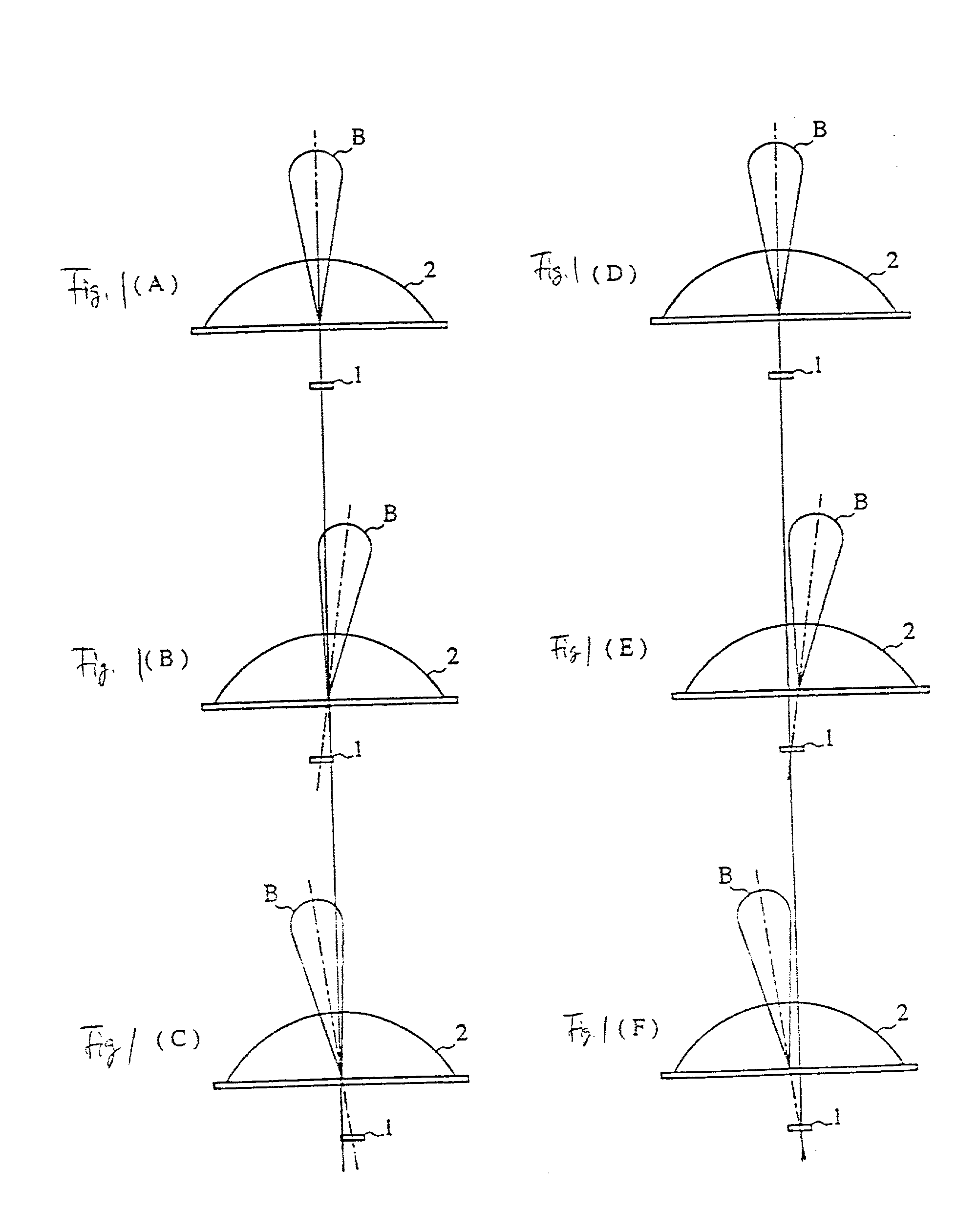
[0050] FIGS. 1A to 1F show the positional relationship between a dielectric lens and a primary radiator, and the relationship with the directivity of a radiation beam. In FIGS. 1A to 1F, reference numeral 1 denotes a primary radiator, with a dielectric lens 2 being disposed with its radiation direction as the center axis. FIGS. 1A, 1B, and 1C show an example in which the dielectric lens 2 is fixed and the primary radiator 1 is movable. As shown in FIG. 1A, when the center axis of the dielectric lens 2 coincides with the radiation direction of the primary radiator 1, a radiation beam B is directed toward the front of the dielectric lens 2. However, when the primary radiator 1 is displaced within the focal plane of the dielectric lens 2 as shown in FIGS. 1B and 1C, the radiation bea...

second embodiment

[0057] Next, the construction of an antenna apparatus and a transmission and receiving apparatus according to the present invention will be described with reference to FIGS. 8 to 14.

[0058] FIG. 8 is a schematic diagram illustrating the construction of the entire transmission and receiving apparatus. In this second embodiment, by displacing the primary radiator 1 in the right-to-left direction in the figure within the housing 3, the radiation beam is tilted in the right-to-left direction in the figure.

[0059] FIGS. 9A, 9B, 9C, and 9D are partial perspective views illustrating the construction of a dielectric line for use in the transmission and receiving apparatus according to the second embodiment of the present invention. In FIGS. 9A, 9B, 9C, and 9D, reference numerals 101 and 102 each denote a conductor plate. In the examples shown in FIGS. 9B and 9D, the dielectric line is formed with a dielectric strip 100 being sandwiched between these two conductor plates. In the examples shown...

fourth embodiment

[0067] FIGS. 16A, 16B, and 16C are plan views showing other examples of a directional coupler in the movable section of an antenna apparatus according to the present invention, with an illustration of the upper and lower conductor plates being omitted. In the example of FIG. 16A, the dielectric strip 12 on the side which couples to the dielectric resonator 11 is formed as a straight line. In the example of FIG. 16B, the dielectric strip 13 on the side which couples to the dielectric resonator 12 is formed as a straight line. In the example of FIG. 16C, one end of the dielectric strip 12 which is coupled at its other end to the dielectric resonator 11 is kept at a fixed distance to and in parallel to the mating dielectric strip 13 up to the end portion.

[0068] FIG. 17 shows an example of the construction of a directional coupler in the movable section of an antenna apparatus according to a fifth embodiment of the present invention. Although in the above-described examples a 0-dB direc...


PUM


Abstract

An antenna apparatus such that a dielectric strip and a dielectric resonator are provided to form a primary vertical radiator, another dielectric strip is provided which is coupled to the dielectric strip to form a directional coupler, and a radiation beam is tilted by changing the relative position of the primary radiator with respect to the dielectric lens by displacing the primary vertical radiator in the directional coupler.

Description

[0001] 1. Field of the Invention[0002] The present invention relates to an antenna apparatus. More particularly, the present invention relates to an antenna apparatus which is used in a radar or the like for transmitting and receiving an electromagnetic wave of a millimetric-wave band and a transmission and receiving apparatus using the same.[0003] 2. Description of the Related Art[0004] Millimetric-wave radars to be mounted in motor vehicles are used in a system for supporting safe driving of automobiles. The millimetric-wave radar is used to measure the distance between two automobiles or between an obstacle in the path of an automobile and the automobile. Based on the measurement data, the speed control and braking of the automobile are performed so that collision into another automobile or an obstacle is prevented.[0005] Generally, a transmission and receiving module using a millimetric-wave radar incorporates a millimetric-wave oscillator, a circulator, a directional coupler, a...

Claims


Application Information

Patent Timeline
IPC IPC(8): H01Q15/02G01S7/02G01S7/03G01S13/34G01S13/42G01S13/931H01Q1/27H01Q3/14H01Q19/00H01Q19/06
CPCG01S7/032G01S13/34G01S13/42G01S13/931G01S2013/9353G01S2013/9375H01Q3/14H01Q19/06H01Q19/062G01S2013/932G01S2013/93271
Inventor ISHIKAWA, YOHEITANIZAKI, TORUNAKAMURA, FUMINORITAKAKUWA, IKUO
Owner MURATA MFG CO LTD
Why Eureka
Try Eureka