Flaw detection system using acoustic doppler effect

a detection system and doppler technology, applied in the direction of instruments, specific gravity measurement, transportation and packaging, etc., can solve the problems of increasing the stress on the rails, not being offset by a proportional increase in the amount of new rail laid, and increasing the risk of fatigue related failures

Inactive Publication Date: 2001-08-23
MASSACHUSETTS INST OF TECH
View PDF0 Cites 11 Cited by
  • Summary
  • Abstract
  • Description
  • Claims
  • Application Information

AI Technical Summary

Benefits of technology

0008] It is therefore an object of this invention to provide a flaw detection ...

Problems solved by technology

Like other transportation modes, however, they are prone to various problems.
Unfortunately, these trends have not been offset with a proportional increase in the amount of new rail laid.
Consequently, the stress on rails and fatigue related failures may continue to increase.
Typical defects often found in railroad tracks include transverse and longitudinal defects in the rail head, web defects, base defects, surface defects as well as other miscellaneous damage such as head wear, corrosion, crushed head, burned rail, bolt hole cracks, head and web separation.
In continuous monitoring, some techniques for inspection of rail flaws at an intermediate speed are currently a...

Method used


Image

  • Flaw detection system using acoustic doppler effect
  • Flaw detection system using acoustic doppler effect
  • Flaw detection system using acoustic doppler effect

Examples


Embodiment Construction

[0023] Other objects, features and advantages will occur to those skilled in the art from the following description of a preferred embodiment and the accompanying drawings, in which:

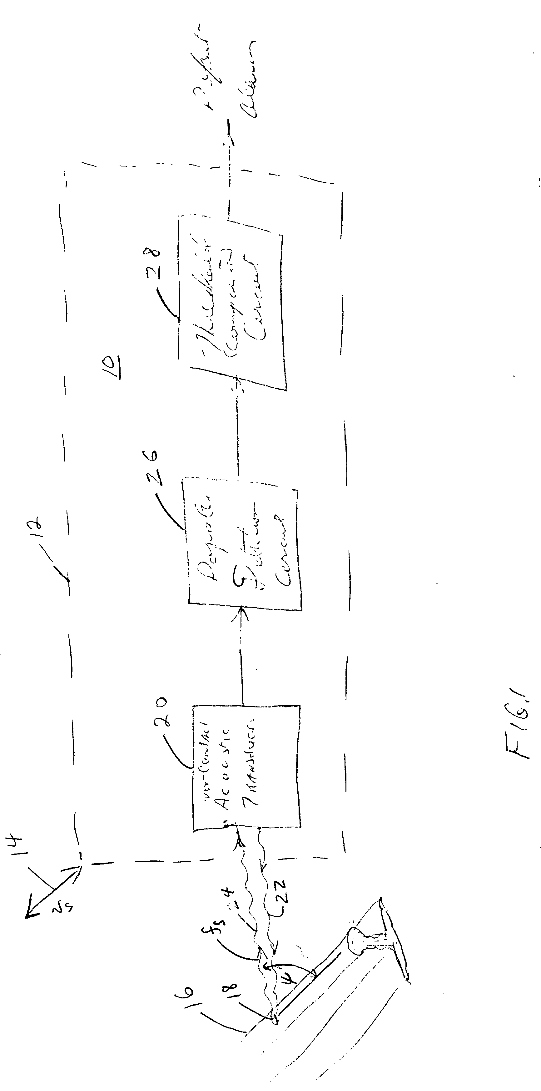
[0024] FIG. 1 is a schematic block diagram of a flaw detection system using acoustic Doppler effect detection system according to this invention adapted to inspect for defects in a railroad rail;

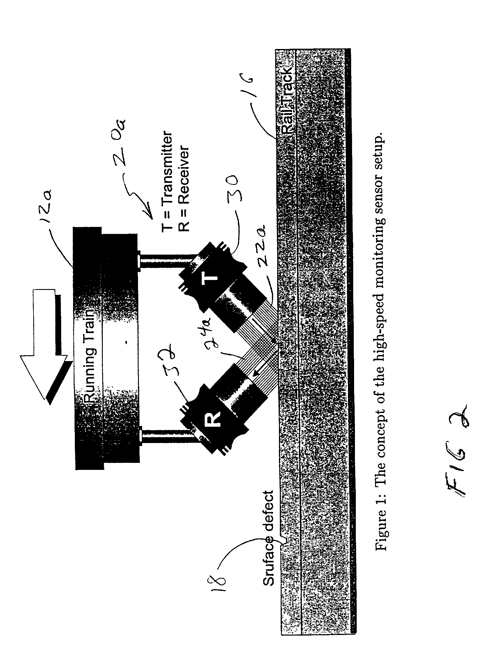
[0025] FIG. 2 is an enlarged detailed view of the acoustic transducer of FIG. 1 implemented with separate receiver and transmitter in the ultrasonic range;

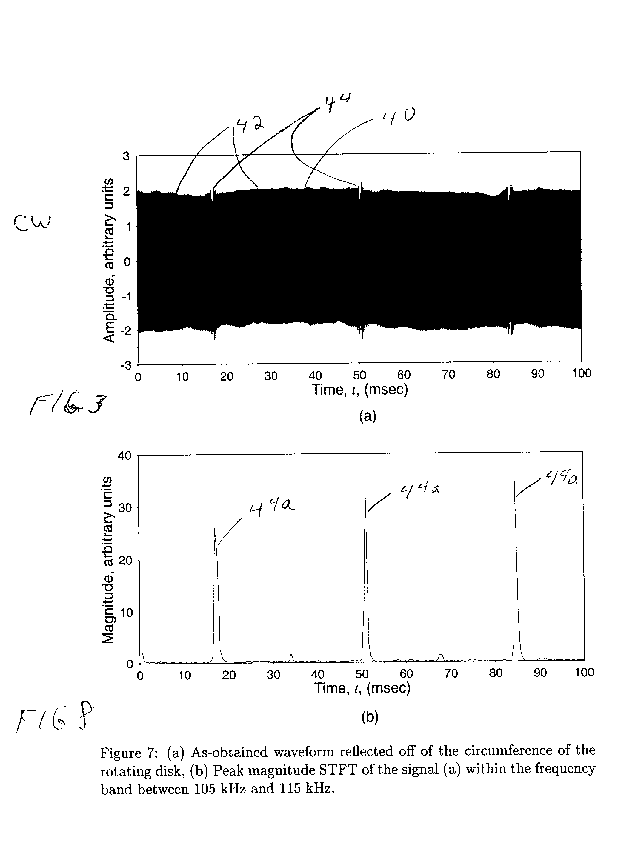
[0026] FIG. 3 illustrates the output signal from the acoustic transducer;

[0027] FIG. 4A illustrates the output carrier signal reflected from the unflawed surface;

[0028] FIG. 4B illustrates the Doppler shifted return signal reflected from a surface flaw;

[0029] FIG. 4C is the magnitude spectrum of the signal reflected from the unflawed surface;

[0030] FIG. 4D is the magnitude spectrum of the reflection from the flaw;

[0031] FIG. 5 is a more detailed block diagram o...


PUM


Abstract

A flaw detection system using acoustic Doppler effect for detecting flaws in a medium wherein there is relative motion between the medium and system includes a transducer, spaced from the medium to be inspected, for introducing to and sensing from the medium an acoustic signal that propagates in the medium at a predetermined frequency; and a detector, responsive to the sensed propagating acoustic signal, for detecting in the sensed acoustic signal the Doppler shifted frequency representative of a flaw in the medium.

Description

[0001] This invention relates to a flaw detection system using acoustic Doppler effect for detecting flaws in a medium to be inspected wherein there is relative motion between the system and medium.BACKGROUND OF INVENTION[0002] Railroads provide both efficiency and economy in passenger and freight transportation. Like other transportation modes, however, they are prone to various problems. Statistics show that over the course of this century, the average carload and trainload tonnage has increased significantly. There is also an increasing concentration of traffic on fewer main line tracks. The average length of haul has also risen. Unfortunately, these trends have not been offset with a proportional increase in the amount of new rail laid. Consequently, the stress on rails and fatigue related failures may continue to increase. With the new demands, it is important to assess the rail integrity by detecting rail defects nondestructively and speedily.[0003] Typical defects often found...

Claims


Application Information

Patent Timeline
IPC IPC(8): G01N29/24G01N29/265G01N29/40G01N29/42
CPCB61K9/10G01N29/2412G01N29/2418G01N29/265G01N29/40G01N29/42G01N2291/017G01N2291/101G01N2291/102G01N2291/2623
Inventor WOOH, SHI-CHANG
Owner MASSACHUSETTS INST OF TECH
Why Eureka
Try Eureka