Rock drill bit having retrac teeth and method for its manufacturing

a drill bit and retracting technology, applied in the field of drill bits, can solve the problems of cracks in teeth, impaired removal of drill bits and drill strings from drilled holes, and sharp corners of teeth

Inactive Publication Date: 2001-09-06
SANDVIK AB
View PDF0 Cites 43 Cited by
  • Summary
  • Abstract
  • Description
  • Claims
  • Application Information

AI Technical Summary

Benefits of technology

0005] One object of the present invention is to provide a rock drill bit of the above-captioned type, wherein the retrac teeth

Problems solved by technology

However, the removal of the drill bit and drill string from the drilled hole is impaired by loose rock material from the bore wall.
However, the shaping of these known teeth at the rear end of the drill bit results in the formation of teeth having sharp c

Method used


Image

  • Rock drill bit having retrac teeth and method for its manufacturing
  • Rock drill bit having retrac teeth and method for its manufacturing
  • Rock drill bit having retrac teeth and method for its manufacturing

Examples


Embodiment Construction

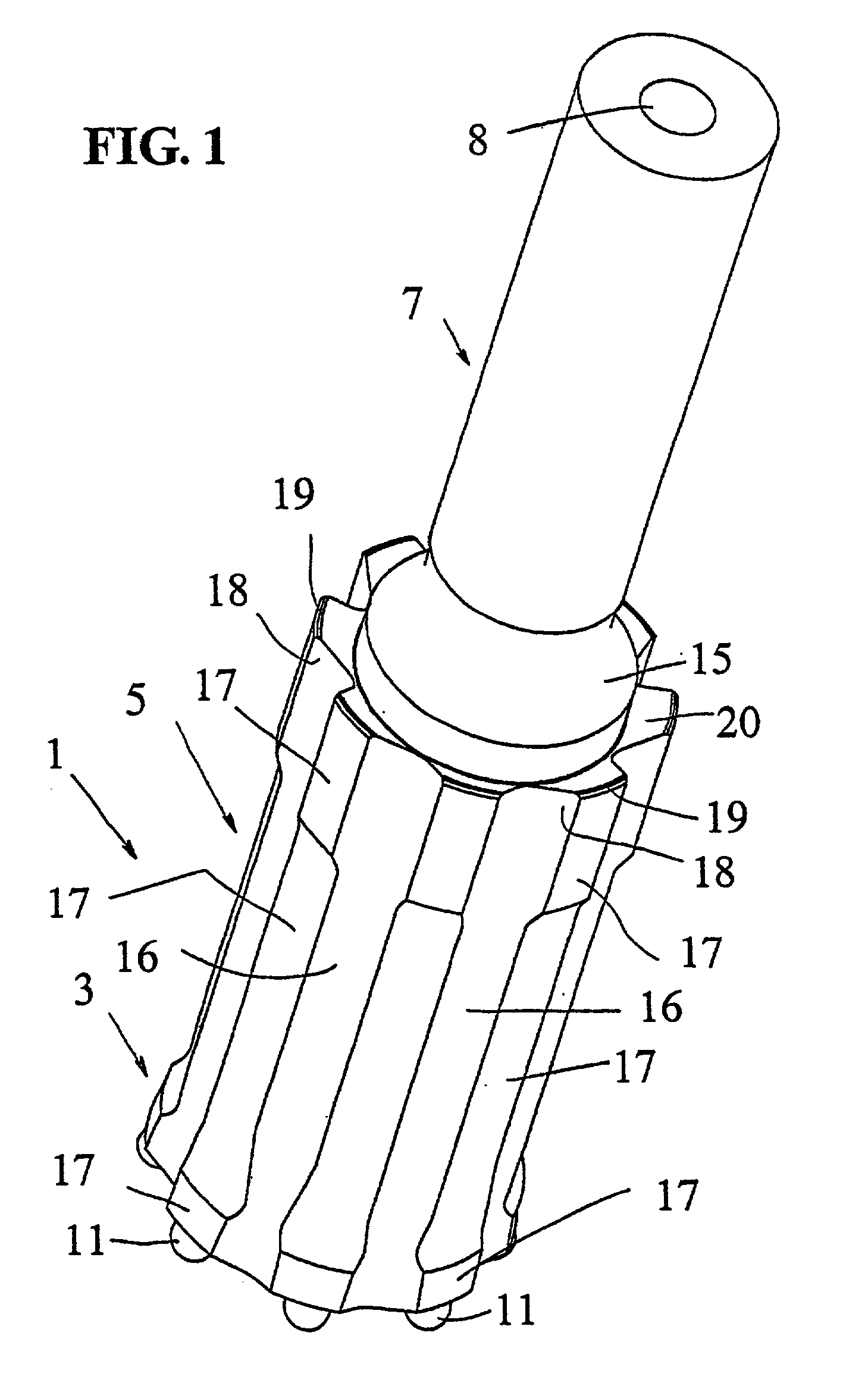
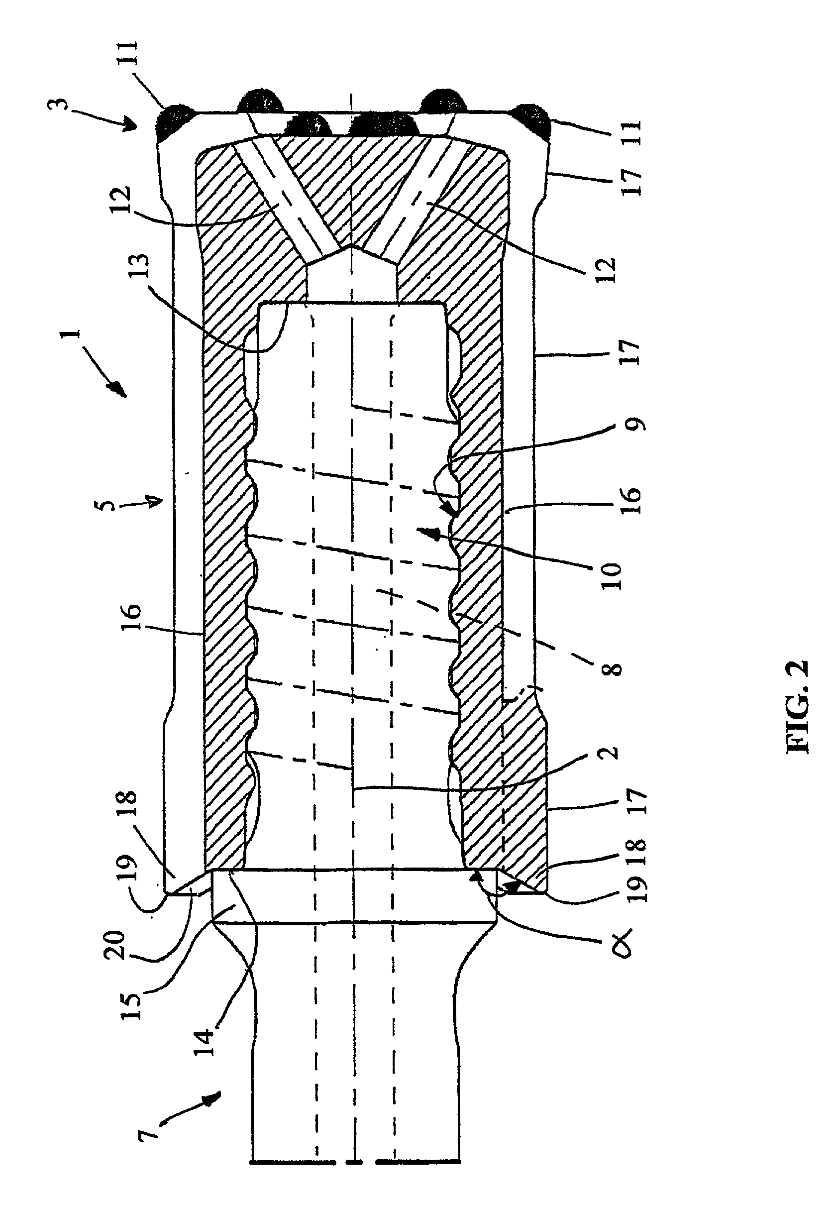
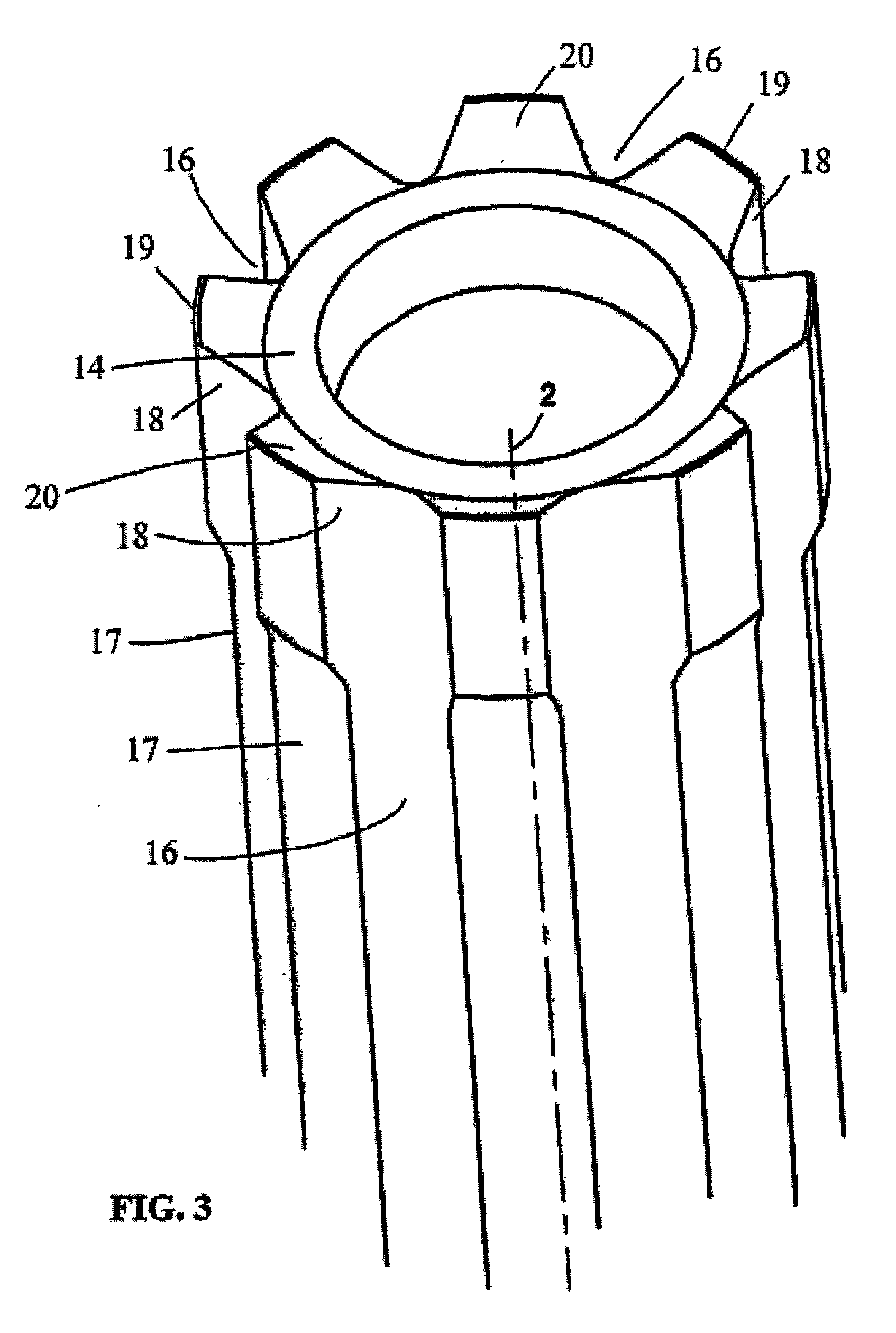
[0013] The drill bit 1 shown in FIGS. 1-3 comprises a bit head 3 and a shank or a skirt 5, said bit head 3 and the skirt 5 being integral with each other. A schematically shown drill rod 7 is connected with the drill bit 1 via a thread joint. A through-going flush channel 8 is in a usual manner provided in the drill rod 7 along a longitudinal center axis 2 common for the drill bit 1 and the drill rod 7.

[0014] As is most visible in FIG. 2, the drill bit 1 is provided with an internal recess having a female thread 9, which receives an external male thread 10 disposed at one end surface of the drill rod 7.

[0015] The bit head 3 of the drill bit 1 according to the present invention is in a usual manner provided with rock crushing means, in the shape of cemented carbide buttons in the shown embodiment, of which several annularly positioned peripheral buttons 11 are shown. Several flushing channels 12 extend between the internal space of the drill bit 1 defined by the female thread 9, and ...


PUM


Abstract

A rock drill bit for percussive drilling, especially top hammer drilling, includes a bit head provided with front rock crushing buttons and a skirt. The bit head is provided with a number of grooves formed in the outside of the skirt and extending in the axial direction of the drill bit. Protruding lands are defined between the grooves, which likewise extend in the axial direction. Axially rearward ends of at least some of the lands are formed with retrac teeth. Each retrac tooth has a cutting edge extending along an outer circumference of the skirt.

Description

RELATED INVENTION[0001] This application claims priority under 35 U.S.C. .sctn..sctn. 119 and / or 365 to Patent Serial No. 0000688-2 filed in Sweden on Mar. 2, 2000, the entire content of which is hereby incorporated by reference.TECHNICAL AREA OF THE INVENTION[0002] The present invention relates to a rock drill bit for percussive drilling, especially for top hammer drilling, and a method for the manufacturing of a rock drill bit.PRIOR ART[0003] A percussive drill bit and its associated drill string comprising drill rods shall be removed from a drilled hole after the hole is completed. During removal, the drill bit and the drill string are usually rotated in an opposite direction compared to the direction employed for drilling of the drilled hole. However, the removal of the drill bit and drill string from the drilled hole is impaired by loose rock material from the bore wall. To correct this problem it is customary that the drill bit has at its rear end, i.e., at the end surface fac...

Claims


Application Information

Patent Timeline
IPC IPC(8): E21B10/00E21B10/36E21B10/38E21B17/042E21B17/10
CPCE21B10/003E21B10/36E21B10/38E21B17/0426E21B17/1092
Inventor ASBERG, BENGTLARSSON, KENNETHEDERYD, BERTIL
Owner SANDVIK AB
Why Eureka
Try Eureka