Actuator and driving method thereof

Inactive Publication Date: 2001-09-13
MINOLTA CO LTD
View PDF0 Cites 11 Cited by
  • Summary
  • Abstract
  • Description
  • Claims
  • Application Information

AI Technical Summary

Benefits of technology

0010] A purpose of the present invention is to provide an actuator and a driving method thereof in which the moving velocity and the torque of

Problems solved by technology

The first conventional actuator, however, has a disadvantage that a variation of an electric power consumption is larger and a burden of an electric power supply becomes larger, since the moving velocity of the driven object is controlled by varying the

Method used


Image

  • Actuator and driving method thereof
  • Actuator and driving method thereof
  • Actuator and driving method thereof

Examples


first embodiment

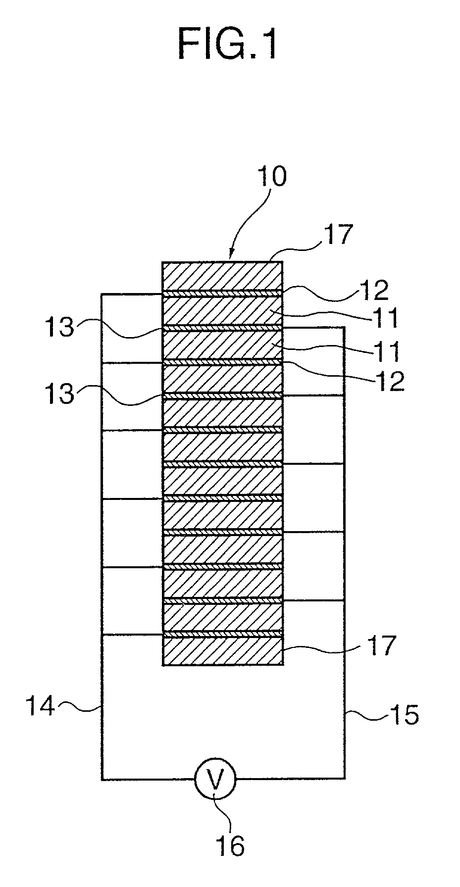
[0053] A first embodiment of an actuator in accordance with the present invention is described. A configuration of a lamination type piezoelectric device used as a displacing device in the following embodiments is shown in FIG. 1. The lamination type piezoelectric device 10 is formed by piling up of a plurality of ceramic thin plates 11 and electrodes 12 and 13 alternately disposed. The ceramic thin plates 11 is made of such as PZT showing piezoelectric characteristic. The ceramic thin plates 11 and the electrodes 12 and 13 are fixed by an adhesive. Two groups of electrodes 12 and 13 which are alternately disposed are respectively connected to a driving power source 16 via cables 14 and 15. When a predetermined voltage is applied between the cables 14 and 15, an electric field is generated in each ceramic thin plate 11 disposed between the electrodes 12 and 13. The direction of the electric field in the ceramic thin plates alternately disposed is the same. Thus, the ceramic thin pla...

second embodiment

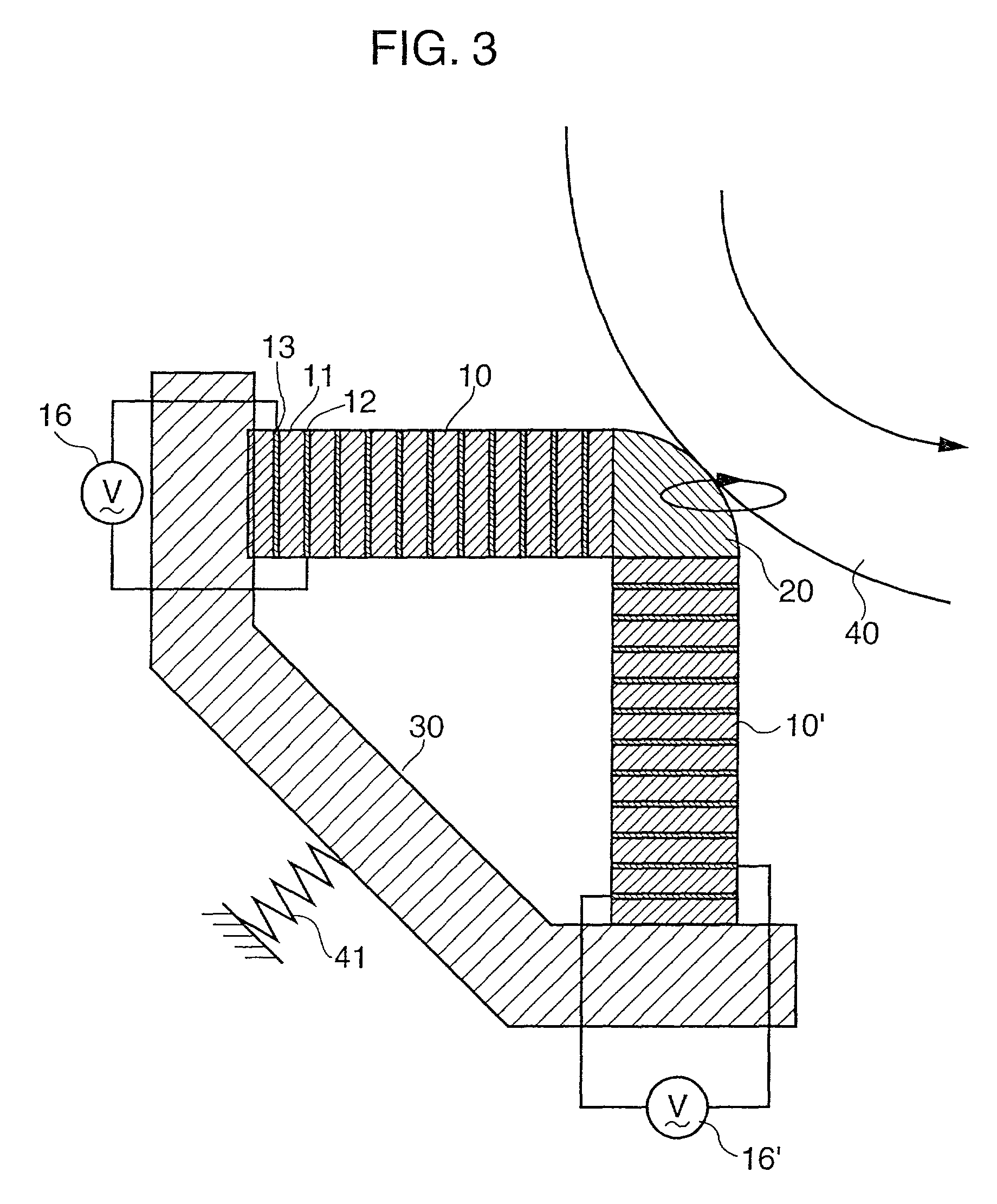
[0077] A second embodiment of an actuator in accordance with the present invention is described. FIG. 10 shows a configuration of a truss-type actuator in the second embodiment. As can be seen from FIG. 10, the first piezoelectric device 10 is arranged in parallel with the normal direction at the contacting point of the chip member 20 with the rotor 40, and the second piezoelectric device 10' is arranged in parallel with the tangential direction. The other elements except the shape of the chip member 20 and the position of the spring 41 are substantially the same as those in the above-mentioned first embodiment.

[0078] A block diagram of a driving circuit is shown in FIG. 11. An oscillator 50 generates a sinusoidal signal having a predetermined frequency coinciding with resonance frequencies of the first piezoelectric device 10 and the second piezoelectric device 10'. A velocity sensor 56 such as a pulse encoder or a magneto-resistive device senses a rotation velocity of the rotor 40...

third embodiment

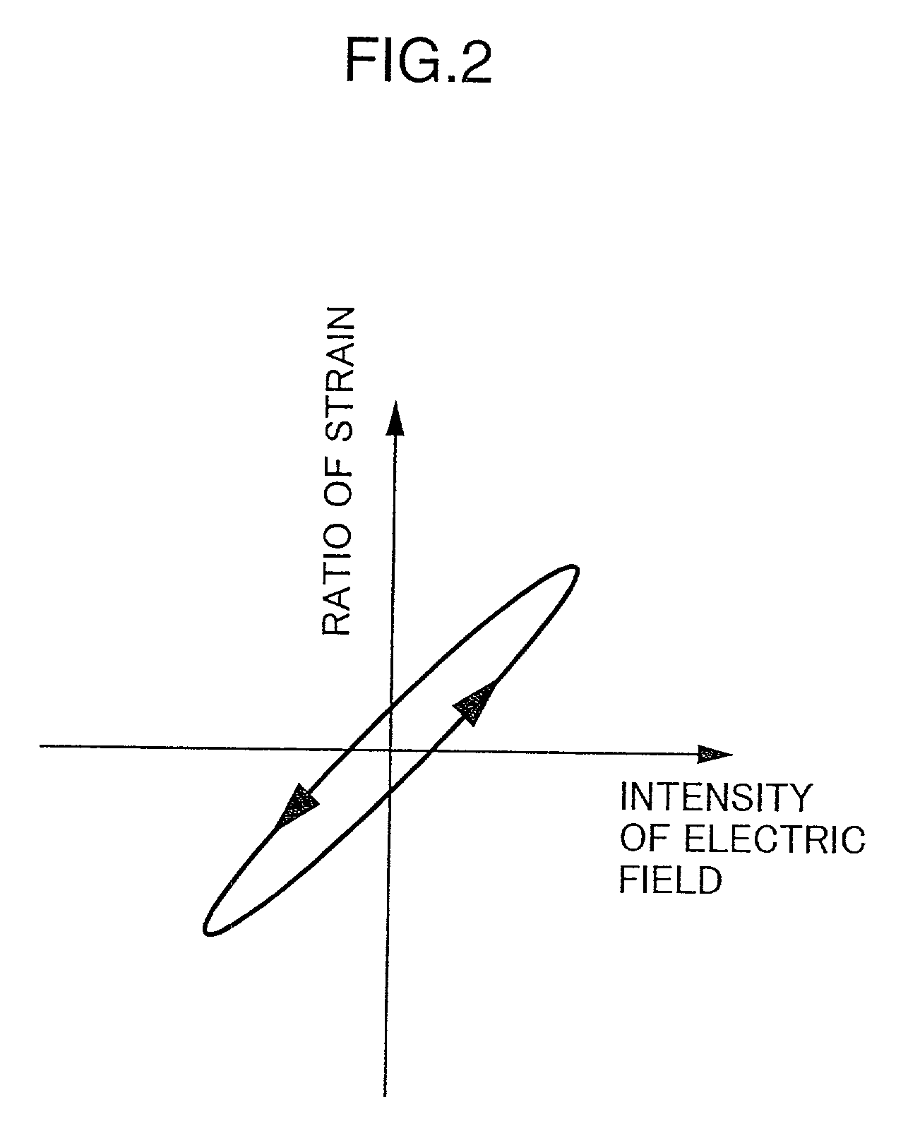
[0080] In the above-mentioned first and second embodiment, the piezoelectric device is used as the displacing device. The ceramics which is a material of the ceramic thin plate has larger damping ratio of the vibrations and the smaller magnification factor of the resonant vibration than those of the metal materials. Furthermore, the ceramics is stronger with respect to the pressure but weaker with respect to the tension, so that it will be separated from the adhered faces in the lamination type piezoelectric device. In a third embodiment, a series connection of a single layered piezoelectric device and an elastic member made of a metal is used as a displacing device.

[0081] A configuration of the actuator in accordance with the third embodiment is shown in FIG. 12. A first displacing device 60 and a second displacing device 60' are respectively configured by single layered piezoelectric devices (ceramic thin plates) 61 and 61', and elastic members 62 and 62'. No electrode is provided...


PUM


Abstract

An actuator includes at least two piezoelectric devices arranged for crossing displacing directions thereof at a predetermined angle, a chip member provided at a coupling point of the piezoelectric devices, and a spring for contacting the chip member to a rotor driven by the actuator. The piezoelectric device is driven for moving the chip member trailing an elliptical trail. The rotation velocity or the driving torque of the rotor is controlled by varying at least one of a length of a major axis or a minor axis of the elliptical trail and an inclination angle of the major axis or the minor axis with respect to a normal at a contacting point of the chip member and the rotor.

Description

[0001] This application is based on patent applications 2000-012568 and 2000-097091 filed in Japan, the contents of which are hereby incorporated by references.[0002] 1. Field of the Invention[0003] The present invention relates to an actuator and a driving method thereof for moving a driven object such as a rotor or a rod by intermittently contacting a driving member to the driven object, in which the driving member is moved for trailing a circular or an elliptical trail by utilizing vibrations of at least one of a plurality of displacing elements such as piezoelectric devices.[0004] 2. Description of the Related Art[0005] In recent years, a truss-type actuator is proposed for rotating or moving a driven object in a predetermined direction. In the truss-type actuator, two displacing elements such as piezoelectric devices are arranged to cross the displacing directions thereof at a predetermined angle such as 90 degrees. The displacing elements are respectively driven by alternating...

Claims


Application Information

Patent Timeline
IPC IPC(8): H01L41/04H01L41/09H02N2/10
CPCH02N2/0025H02N2/103H02N2/142
Inventor MATSUO, TAKASHIUEYAMA, MASAYUKIOKADA, HIROYUKISHIBATANI, KAZUHIROMATSUDA, SHINYAKOSAKA, AKIRA
Owner MINOLTA CO LTD
Why Eureka
Try Eureka