Hydraulic control system for a continuously variable transmission

a technology of continuously variable transmission and hydraulic control system, which is applied in the direction of climate sustainability, gearing elements, and gas mileage drop, etc., to achieve the effect of less frictional loss

Inactive Publication Date: 2001-09-20
JATCO LTD
View PDF0 Cites 61 Cited by
  • Summary
  • Abstract
  • Description
  • Claims
  • Application Information

AI Technical Summary

Benefits of technology

0034] In another aspect of the invention, the shift control means is operable to reduce the raised line pressure to the first level once it is determined that the shift to the HI side is accomplished after raising the line pressure. Thus, except the minimum period of time taken to attain the shift to the HI side, the hydraulic pressure applied to the transmission mechanism is normally maintained at a low level providing the less frictional loss.

Problems solved by technology

Greater line pressure than is necessary may give rise to an increased frictional loss at the contact area between the V-belt 24 and each of the pulleys 16 and 26, which in turn can lead to a drop in gas mileage.
However, at the relatively low degree of depression of the accelerator pedal or the relatively low (e.g. on the order of {fraction (1 / 8)}) throttle opening degree, the CVT may undesirably retard, possibly discontinue, its shift to the transmission rate on the HI side (sometimes referred to as "upshift" hereinafter) and as a result the available range of the transmission ratio will become actually narrowed.

Method used


Image

  • Hydraulic control system for a continuously variable transmission
  • Hydraulic control system for a continuously variable transmission
  • Hydraulic control system for a continuously variable transmission

Examples


Embodiment Construction

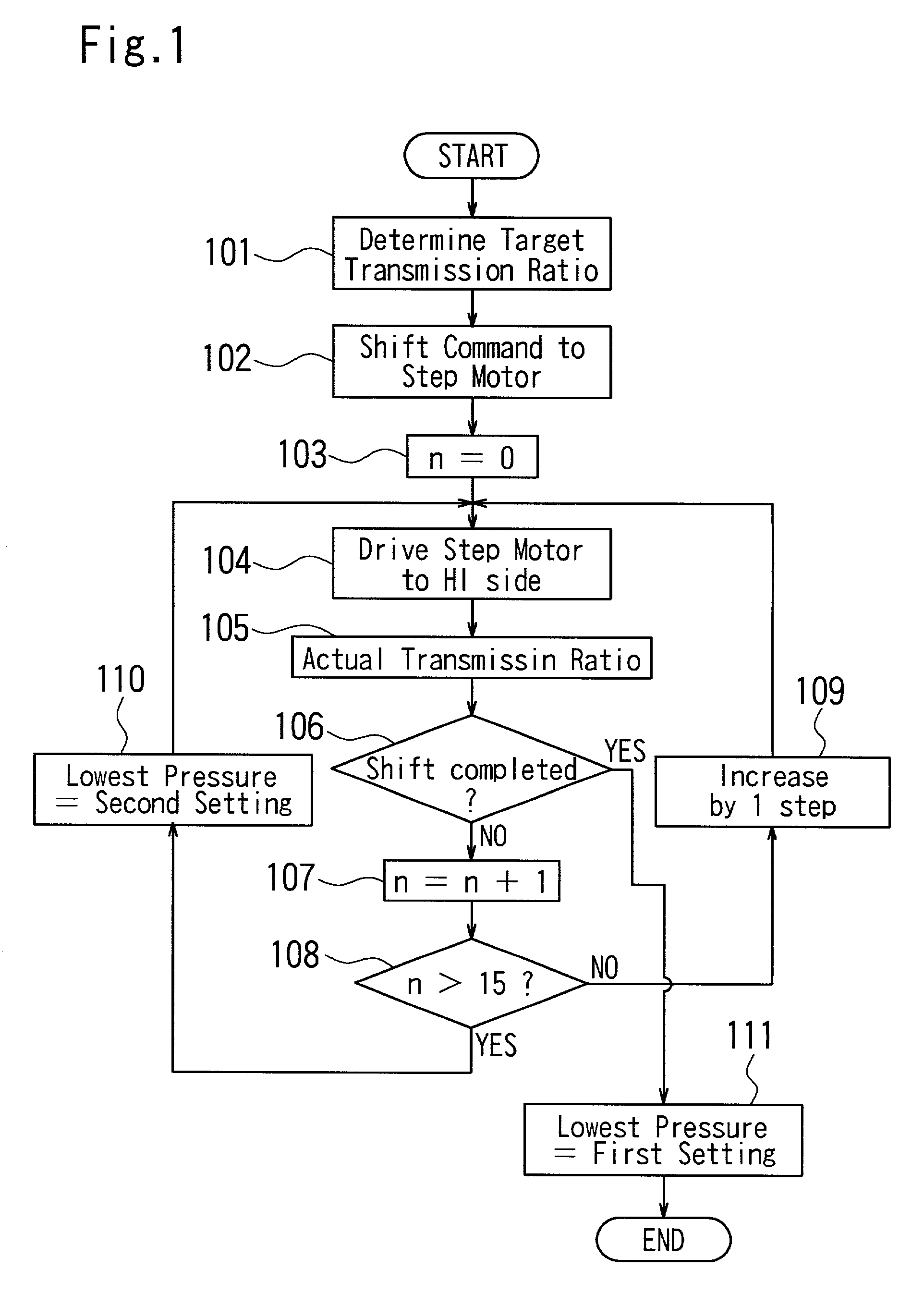
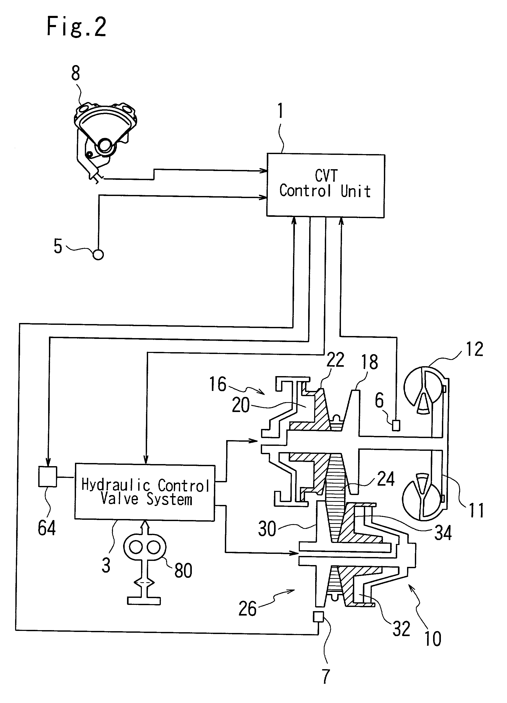
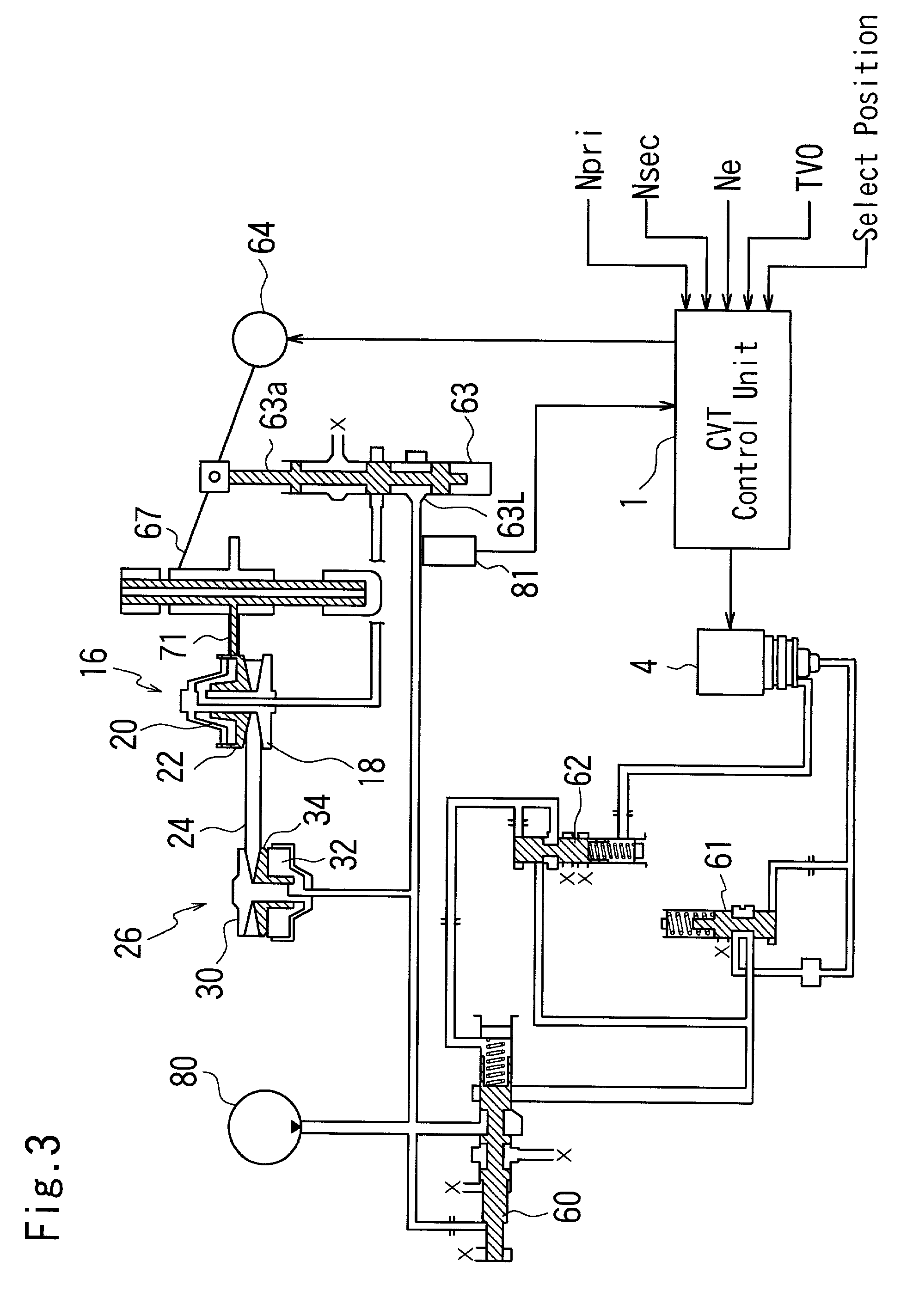
[0038] Description will now be made in detail of an embodiment according to the present invention as applied to the conventional arrangement shown in FIGS. 2 and 3 and outlined above. In the normal control, the minimum line pressure to be established by the CVT control unit 1 is at a first pressure setting, which is the lowest value in consistent with the torque being transmitted. The control unit 1 is operable to change the minimum line pressure to a second pressure setting which is higher than the first setting when the upshift to HI side operation through the control of the step motor 64 would fail to establish the target transmission ratio. Other structure and operation of various components of the system are same as those shown in FIGS. 2 and 3, and reference should be made to the above mentioned Japanese Patent Application Laid Open No. 11-82725.

[0039] FIG. 1 is a flow chart showing a shift control process or program performed by the CVT control unit 1 and the operation of the...


PUM


Abstract

A transmission mechanism of the continuously variable transmission comprises a set of primary and secondary pulleys between which a belt is provided. The CVT control unit is operable to supply line pressure directly to a secondary pulley and also to a primary pulley via a shift control valve associated with a step motor in such a manner as to control a transmission ratio. The CVT control unit calculates a standard step position of the step motor corresponding to the target transmission ratio and provides a command signal representative of a difference between the standard step position and the current position of the step motor. The shift control valve actuated by the step motor controls the pressure to be supplied to the primary pulley. The actual transmission ratio obtained on the basis of the rotation speeds of the pulleys is compared with the target transmission ratio. If the shift is not accomplished, the CVT control unit commands additional step number. Unless the shift to the HI side is accomplished at the time when the additional step number reaches the threshold value, the line pressure is increased so as to achieve the shift. Thus, the transmission normally operates with a low line pressure sufficiently to reduce a frictional loss at the contact areas of the belt and the pulleys, thereby resulting in an enhanced fuel economy.

Description

[0001] 1. Field of the Invention[0002] The present invention relates in general to a continuously variable transmission of the type employing a V-belt for use in a vehicle or the like, and more particularly to improvements in a hydraulic control system for the same.[0003] 2. Description of the Prior Art[0004] A V-belt type continuously variable transmission (CVT) suitable for vehicle applications is disclosed in, for example, Japanese Patent Application Laid Open No. 11-82725.[0005] In such a V-belt type continuously variable transmission, a V-belt passes about a primary pulley which is coupled to an engine and a secondary pulley which is coupled to the wheel axle of the vehicle. The groove width of the primary pulley is variably controlled by the supply of hydraulic pressure. The general construction of the transmission together with a conventional hydraulic control system therefor is shown in FIGS. 2 and 3.[0006] The transmission mechanism 10 comprises a primary pulley 16, a secon...

Claims


Application Information

Patent Timeline
Patent Type & Authority Applications(United States)
IPC IPC(8): F16H9/00F16H61/00F16H61/06F16H61/662
CPCF16H61/66259Y02T10/76Y10T477/624Y10T477/69395Y10T477/6242F16H61/66F16H61/06
Inventor MIYAGAWA, YOSHIKAZUSAKAKIBARA, SATOSHI
Owner JATCO LTD
Why Eureka
Try Eureka