Electromagnetic wave assisted chemical processing

a technology of electromagnetic wave and chemical processing, applied in the field of material processing, can solve the problems of limited absorption efficiency, poor interior volume, and very hot outer parts of materials

Inactive Publication Date: 2001-10-18
KREIDO LAB +1
View PDF0 Cites 32 Cited by
  • Summary
  • Abstract
  • Description
  • Claims
  • Application Information

AI Technical Summary

Problems solved by technology

In household applications, the frequency chosen for microwave ovens is about 2.5 GHz, which provides for a limited efficiency of absorption.
The outer portions of the materials would become very hot, but the interior volume would be poorly heated.
The processing takes place in relatively small batches, and as such is not feasible for production of industrial quantities of processed materials.
There have been no practical microwave-assisted reactor that can produce relatively large quantities of materials in a continuous process.
This would reduce the possibility of non-homogeneous reactions resulting in the production of undesirable by-products or results caused by uneven heating and mixing.
However, the tubes quickly become covered in slime or other contaminates, reducing the emitted ultraviolet radiation to a level where some pathogens can survive, leading to possible illness or death when the water is consumed.

Method used


Image

  • Electromagnetic wave assisted chemical processing
  • Electromagnetic wave assisted chemical processing
  • Electromagnetic wave assisted chemical processing

Examples


Embodiment Construction

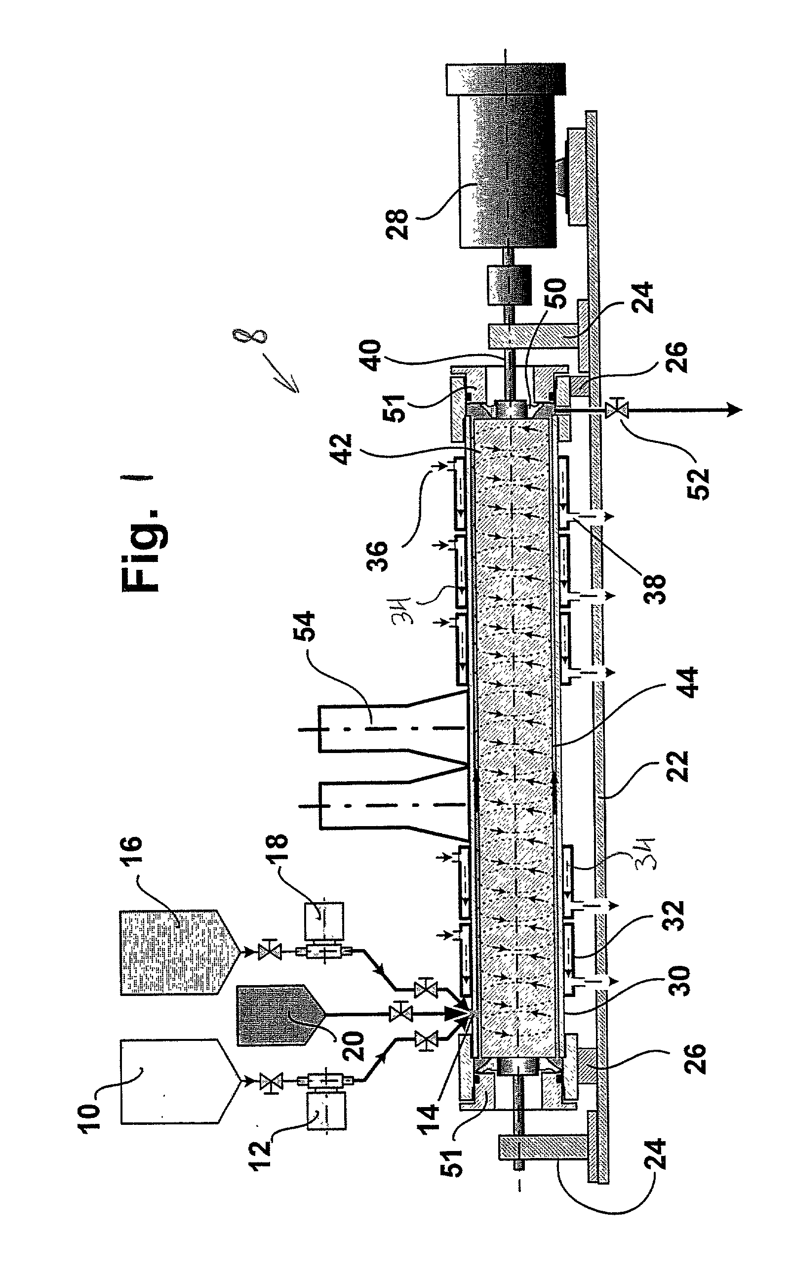
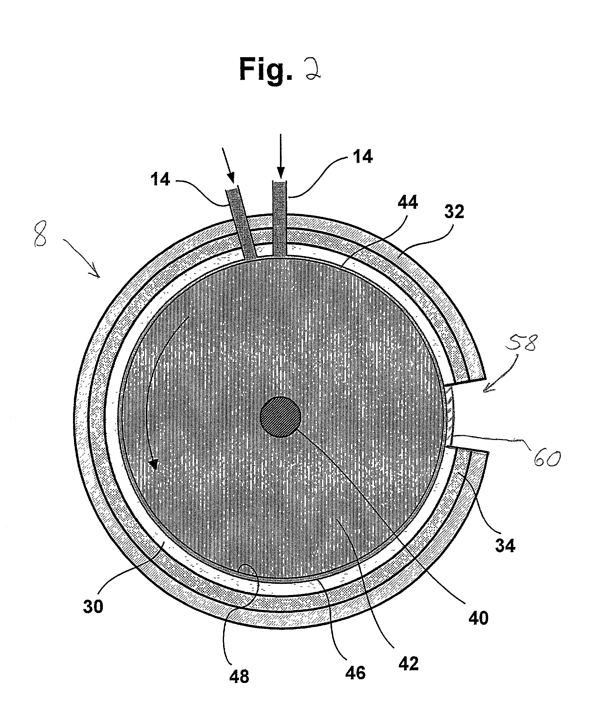
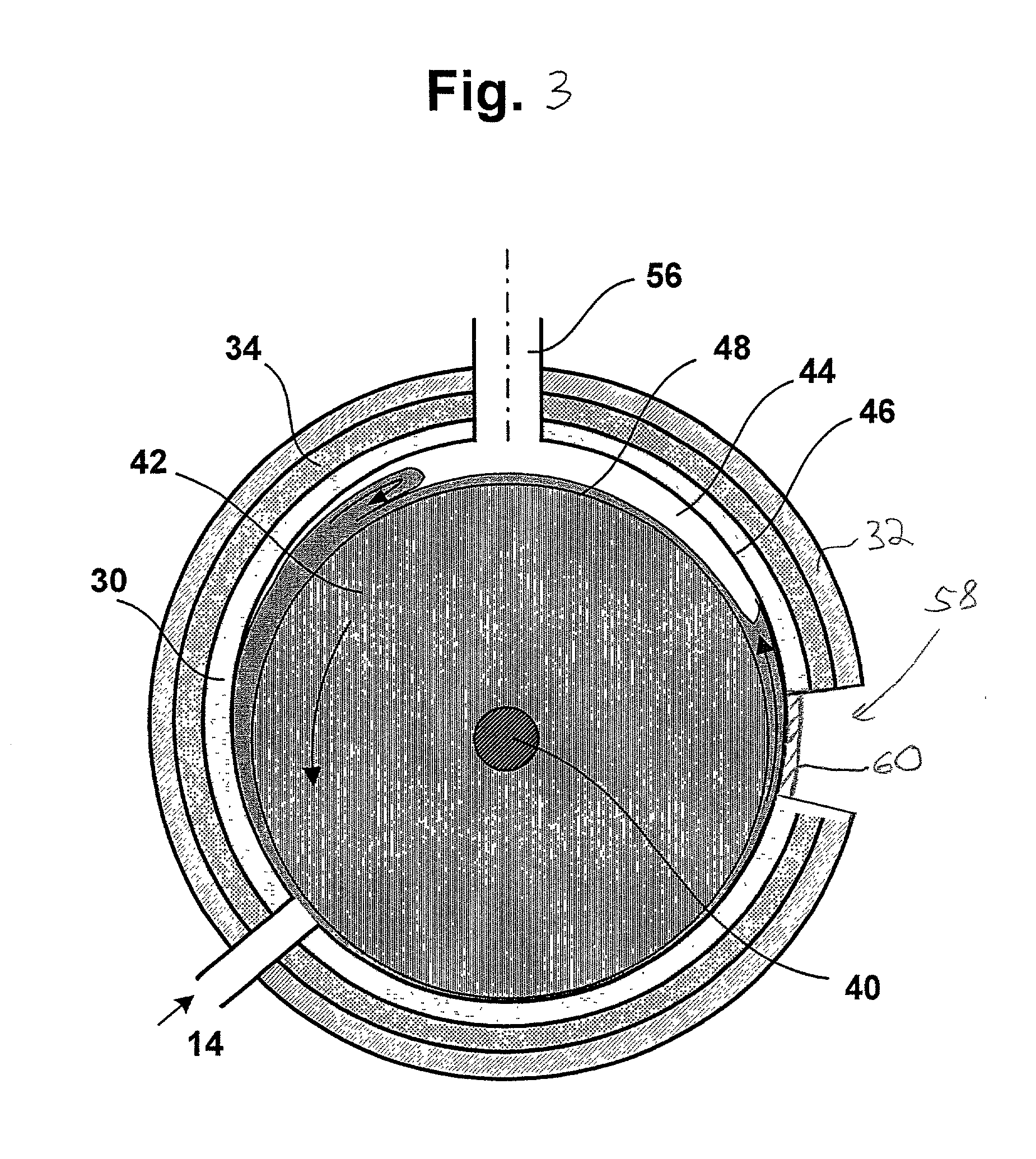
[0019] In a reactor 8 illustrated by FIGS. 1 and 2, a first reactant (Reactant A) is fed from a supply tank 10 via a metering pump 12 to inlet 14, while a second reactant (Reactant B) is fed from a supply tank 16 via a metering pump 18 to the same inlet 14. If required, an optional catalyst or reactant gas is fed from a supply tank 20 to the inlet 14. If separate inlets 14 are used then they must be in close tangential proximity to one another. The processing apparatus comprises a baseplate 22 on which is mounted rotor bearing supports 24, stator supports 26 and a variable speed electric drive motor 28. An outer cylindrical apparatus member or cylindrical tube 30 comprising the apparatus stator is mounted on supports 24, and in turn supports along the major portion of its length another cylindrical tube 32 constituting the outer casing of a heat exchanger through which gas or liquid can be passed to control the temperature in the processing chamber. The annular passage 34 between th...


PUM

PropertyMeasurementUnit
linear velocityaaaaaaaaaa
frequencyaaaaaaaaaa
frequencyaaaaaaaaaa

Abstract

A window allows the introduction of radiation energy into an annular processing chamber filled with a material to be processed. The chamber is formed from coaxial cylinder members rapidly rotating relative to one another. The chamber can be thin enough so that it is short compared to the penetration depth of the radiation through the material, providing even exposure of the material to the radiation. Also, eddies created in the material by the relative rotation enhances the even exposure. When the material inside the annular processing chamber is opaque, resulting in an insignificant penetration depth, the eddies still insure that the material is evenly exposed to the irradiation.

Description

[0001] 1. Field of the Invention:[0002] The present invention relates to materials processing involving a chemical and / or a physical action(s) or reaction(s) of a component or between components. More specifically, the present invention uses irradiation of components in a reactor to continuously process relatively large quantities of materials.[0003] 2. General Background and State of the Art:[0004] Apparatus for materials processing consisting of coaxial cylinders that are rotated relative to one another about a common axis, the materials to be processed being fed into the annular space between the cylinders, are known. For example, U.S. Pat. No. 5,370,999, issued Dec. 6, 1994 to Colorado State University Research Foundation discloses processes for the high shear processing of a fibrous biomass by injecting a slurry thereof into a turbulent Couette flow created in a "high-frequency rotorstator device", this device having an annular chamber containing a fixed stator equipped with a ...

Claims


Application Information

Patent Timeline
Patent Type & Authority Applications(United States)
IPC IPC(8): B01F7/00B01F13/00B01F13/10B01F15/00B01J19/08B01J19/10B01J19/12B01J19/18B29B7/40B29B7/90B29C48/38C02F1/30C02F1/32C02F1/36C08K3/00F28D11/02H05K1/03H05K3/02
CPCB01F7/005B01F7/008B01F13/0001B01F15/00714B01F15/00909B01F2013/1086B01J19/082B01J19/10B01J19/122B01J19/125B01J19/126B01J19/127B01J19/18B01J19/1887B01J2208/00B01J2219/00094B01J2219/00141B01J2219/00146B01J2219/00164B01J2219/00166B01J2219/00168B01J2219/0888B01J2219/1227B01J2219/182B01J2219/1943B22F2998/00B29B7/401B29B7/90B29C47/0009B29C47/50B29K2021/00B29K2105/16B29K2503/04C02F1/30C02F1/302C02F1/32C02F1/36C08K3/0008F28D11/02C22C32/0094C08K3/01B29C48/03B29C48/38B01F27/116B01F27/272B01F33/05B01F33/83613B01F35/4122B01F35/54
Inventor HOLL, RICHARD A.
Owner KREIDO LAB
Why Eureka
Try Eureka