Actuating system comprising a piston-cylinder assembly together with a driving device

a technology of piston cylinder and driving device, which is applied in the direction of superstructure subunits, position/direction control, ac motor stoppers, etc., can solve the problems of reducing the service life of the clutch lock

a technology of piston cylinder and driving device, which is applied in the direction of superstructure subunits, position/direction control, ac motor stoppers, etc., can solve the problems of reducing the service life of the clutch lock

US20010035725A1Inactive Publication Date: 2001-11-01STABILUS

Image

  • Actuating system comprising a piston-cylinder assembly together with a driving device
  • Actuating system comprising a piston-cylinder assembly together with a driving device
  • Actuating system comprising a piston-cylinder assembly together with a driving device

Examples


Embodiment Construction

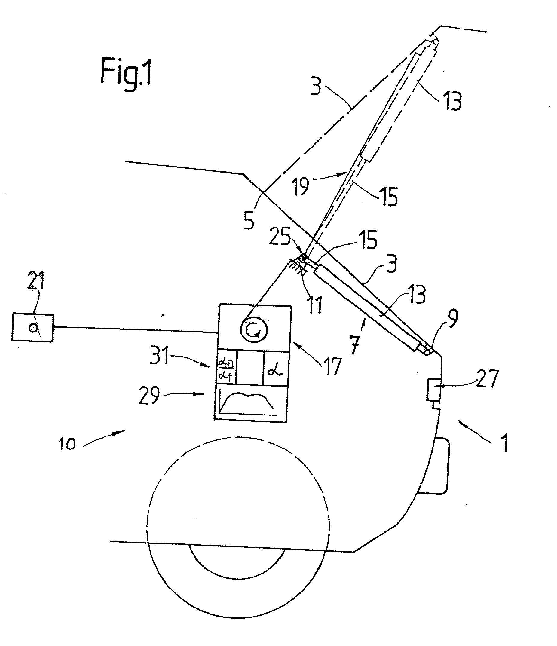
[0044] FIG. 1 shows a schematic diagram of a motor vehicle having a vehicle body as the base part 1 and a movable part 3 in the form of a rear flap, hereinafter a flap, although it may also be a hood, a vehicle door or corresponding cases of use.

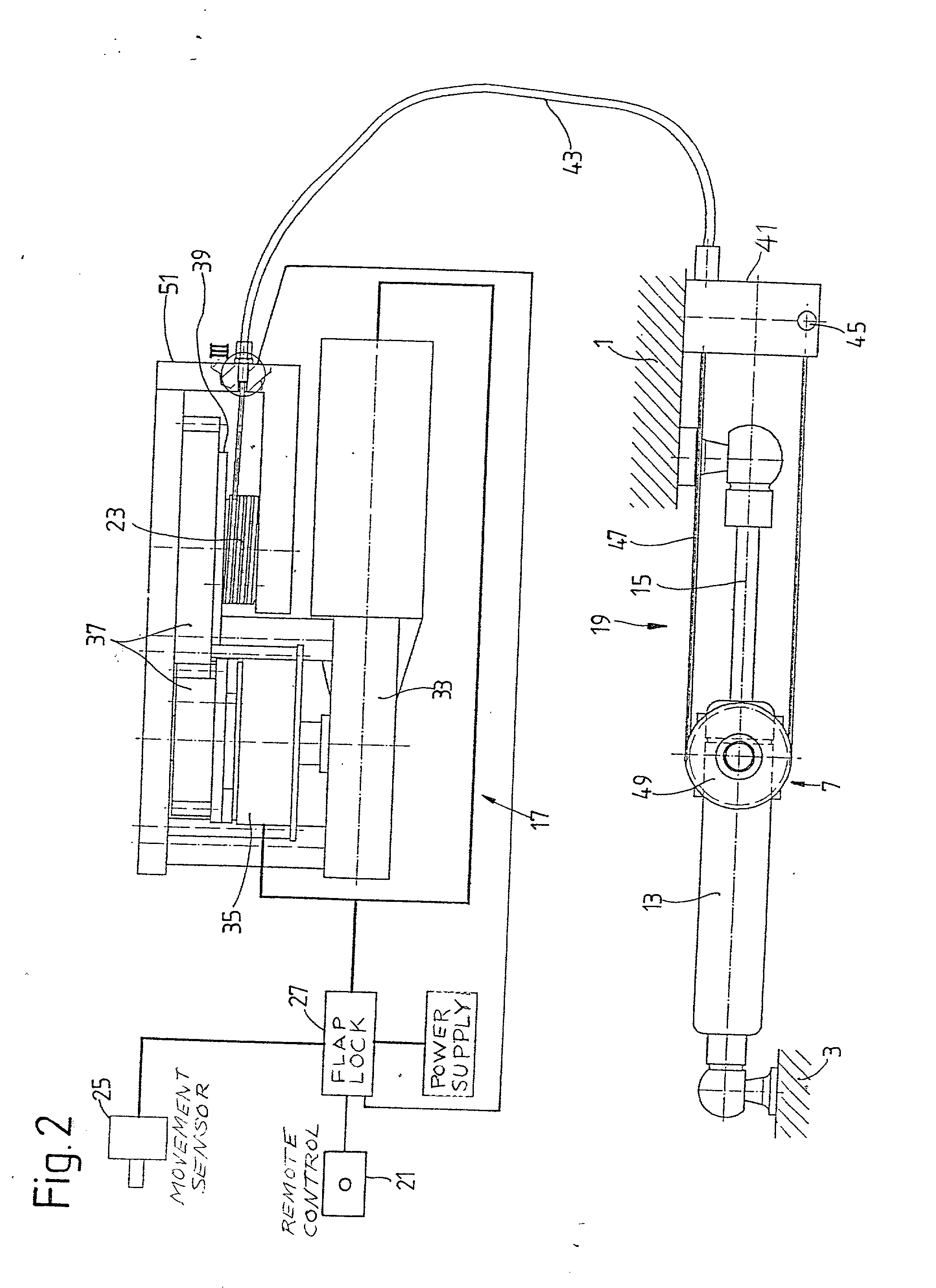
[0045] The flap 3 is pivotably mounted at an axis 5 running transversely to the vehicle. At least one piston-cylinder assembly 7 exerts a force in the opening direction on the flap 3. The piston-cylinder assembly is preferably a gas-filled spring device optionally having end position damping. The piston-cylinder assembly 7 is fastened to the base part 1 and to the flap 3 via connecting members 9, 11. The main components of the piston-cylinder assembly are a cylinder 13 and a piston rod 15. For example, a piston-cylinder assembly according to U.S. Pat. Nos. 4,466,514 or 4,595,182 could be used.

[0046] The flap is closed by an actuating system 10 which comprises a driving device 17. This driving device is operatively connected to the flap 3 via...


PUM


Abstract

An actuating system includes a driving device fixed to a base part and operatively connected to a movable part. A sensor detects the rotational speed of the movable part at a reference measuring location, and a control system forms a differential of the rotational speed with respect to the time. The formed differential is compared in a comparison unit with a stored differential value which corresponds to a measuring point on a route of movement of the movable part. An obstacle is recognized when there is a difference above a threshold value between the formed differential and the associated stored value.

Description

[0001] 1. Field of the Invention[0002] The invention relates to an actuating system in accordance with the preamble of patent claim 1.[0003] 2. Description of the Related Art[0004] U.S. Pat. No. 5,982,126 discloses a control arrangement for a driven locking means, the control arrangement being provided for flaps or doors in a motor vehicle. The control arrangement includes, among other things, a piston-cylinder assembly which exerts an opening force on a rear flap or a vehicle door. Furthermore, a driving unit in the form of an electric motor provides, in conjunction with a cable device, a closing movement of the rear flap or the vehicle door.[0005] The control arrangement includes obstacle recognition providing protection against jamming. For this, the power or the current of the electric motor is sensed and compared with data records which represent the movement of the vehicle door or of the rear flap. The movement is stored in accordance with parameters of the absolute closing fo...

Claims


Application Information

Patent Timeline
01 Nov 2001
Publication
US20010035725A1
IPC
B62D25/12; E05F1/10; E05F15/00; E05F15/12
CPC
B62D25/12; E05F15/627; E05Y2201/246; E05Y2201/416; E05Y2201/462; E05Y2400/326; E05Y2400/36; E05Y2400/55
Inventors
MINTGEN, ROLF; RISSEL, RALF