Application of light at plural treatment sites within a tumor to increase the efficacy of light therapy

a tumor and light therapy technology, applied in the field of light therapy, can solve the problems of concomitant effect and concomitant effect, and achieve the effect of destroying quickly

Inactive Publication Date: 2002-01-24
LIGHT SCI ONCOLOGY
View PDF0 Cites 52 Cited by
  • Summary
  • Abstract
  • Description
  • Claims
  • Application Information

AI Technical Summary

Benefits of technology

0020] The method may include further steps. Specifically, in one embodiment, the light is emitted into the tumor in a first direction from each of the plurality of probes, relative to the probe from which the light is emitted. Next, the method provides for terminating emission of light into the tumor in the first direction and emitting light into the tumor in a second direction from each of the plurality of probe

Problems solved by technology

Furthermore, the extended period of light therapy indirectly destroys the substantial portion of the tumor that is not penetrated by the light being administered by inducing at least one concomitant effect that destroys the abnormal tissue comprising the substantial portion of the tumor.
In one case, the concomitant effect arises because the destruction of

Method used


Image

  • Application of light at plural treatment sites within a tumor to increase the efficacy of light therapy
  • Application of light at plural treatment sites within a tumor to increase the efficacy of light therapy
  • Application of light at plural treatment sites within a tumor to increase the efficacy of light therapy

Examples


Embodiment Construction

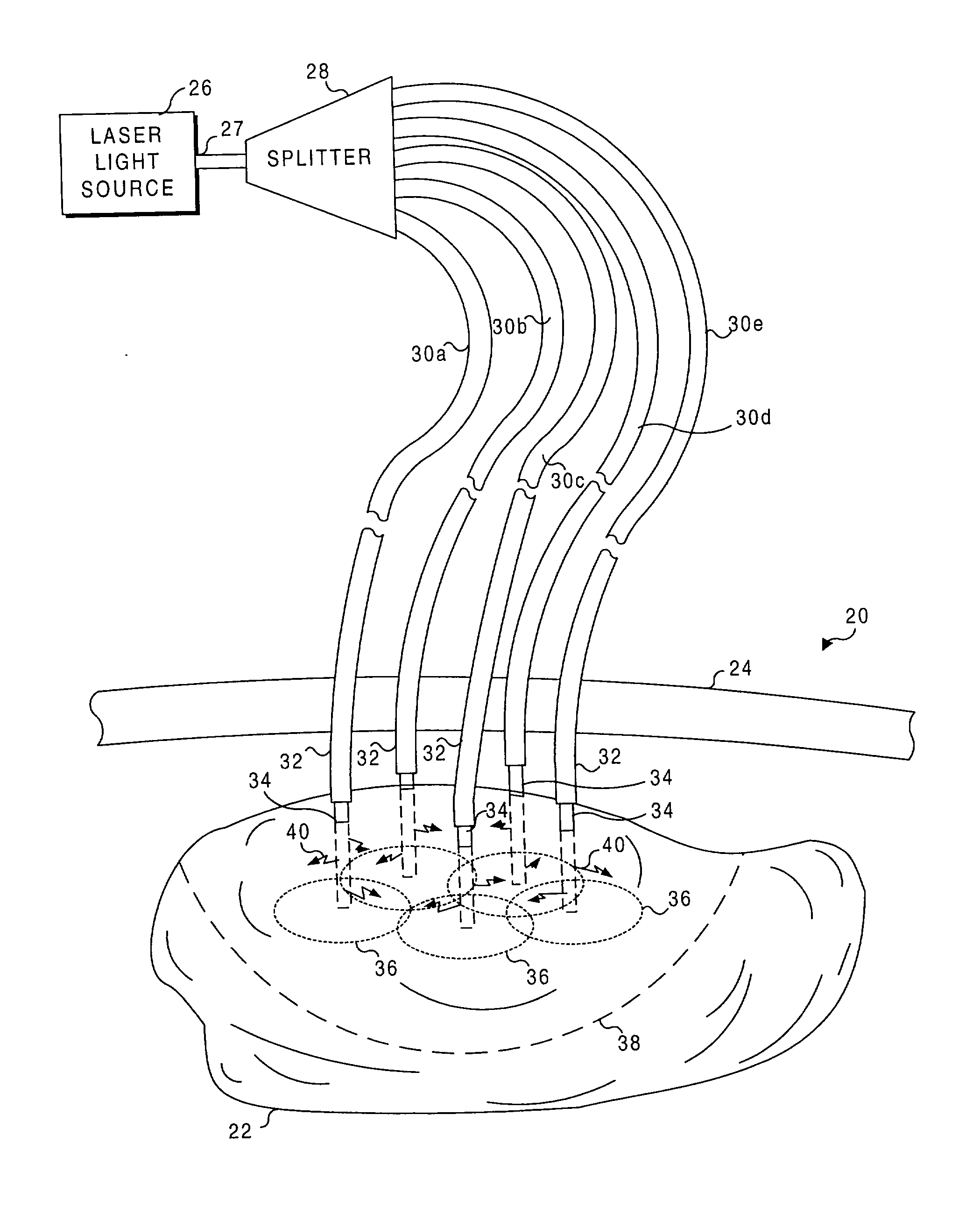
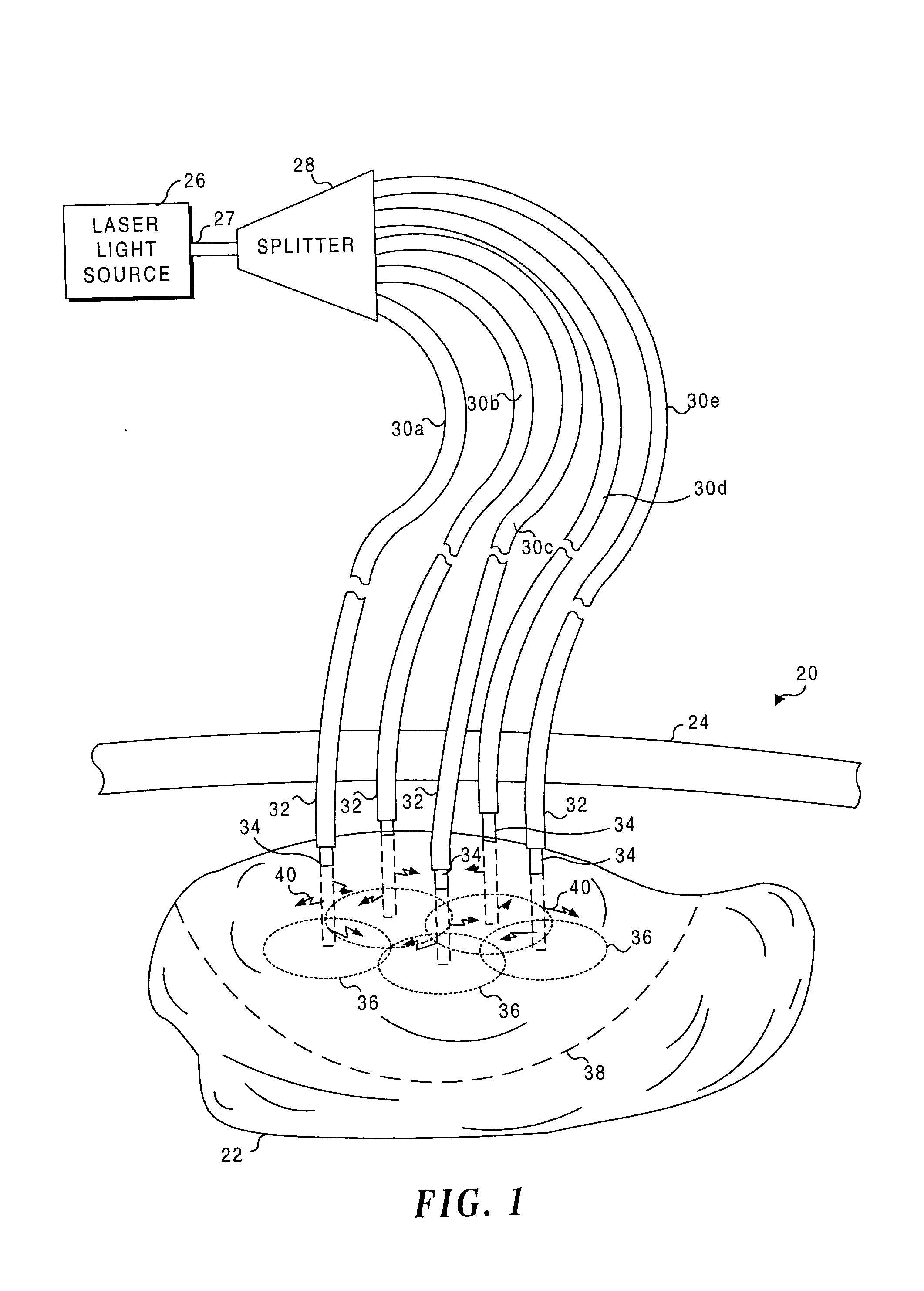
[0036] With reference to FIG. 1, the present invention is illustrated in connection with treating a tumor 22 that is disposed within a patient's body 20. Tumor 22 is relatively large, having a length of approximately 7 to 10 cm and a transverse width of about 7 cm in this exemplary illustration. The tumor is disposed below a dermal layer 24, for example, within the patient's abdominal cavity.

[0037] In the present invention, PDT plays an important role is destroying abnormal tissue comprising tumor 22. As is done when rendering conventional PDT, a photoreactive agent is administered to the patient either orally or by injection and is selectively preferentially absorbed by the abnormal tissue of tumor 22. Thereafter, using a surgical procedure to access tumor 22 through dermal layer 24, or using an endoscopic procedure with minimally invasive impact, a plurality of optical fibers 30a-30e are inserted into the interior of tumor 22 in a spaced-apart array so that the optical fibers are ...


PUM


Abstract

Light is administered during photodynamic therapy (PDT) for an extended period of time at a plurality of sites distributed within the abnormal tissue of a tumor. A clinical study has shown that a substantially greater volume of abnormal tissue in a tumor is destroyed by the extended administration of light therapy from a plurality of probes than would have been expected based upon the teaching of the prior art. In this process, a plurality of light emitting optical fibers or probes are deployed in a spaced-apart array. After a photoreactive agent is absorbed by the abnormal tissue, the light therapy is administered for at least three hours. The greater volume of necrosis in the tumor is achieved due to one or more concomitant effects, including: the inflammation of damaged abnormal tissue and resultant immunological response of the patient's body; the diffusion and circulation of activated photoreactive agent outside the expected fluence zone, which is believed to destroy the abnormal tissue; a retrograde thrombosis or vascular occlusion outside of the expected fluence zone; and, the collapse of the vascular system that provides oxygenated blood to portions of the tumor outside the expected fluence zone. In addition, is possible that molecular oxygen diffusing and circulating into the expected fluence zone is converted to singlet oxygen during the extended light therapy, causing a gradient of hypoxia and anoxia that destroys the abnormal tissue outside the expected fluence zone.

Description

FIELD OF THE INVENTION[0001] The present invention generally relates to the use of light therapy to destroy abnormal tissue in a tumor, and more specifically, to the use of multiple light sources disposed at spaced-apart treatment sites within a tumor to render the therapy.BACKGROUND OF THE INVENTION[0002] Abnormal tissue in the body is known to selectively absorb certain dyes that have been perfused into a treatment site to a much greater extent than surrounding tissue. For example, tumors of the pancreas and colon may absorb two to three times the volume of these dyes, compared to normal tissue. Once pre-sensitized by dye tagging in this manner, the cancerous or abnormal tissue can be destroyed by irradiation with light of an appropriate wavelength or waveband corresponding to an absorbing wavelength or waveband of the dye, with minimal damage to normal tissue. This procedure, which is known as photodynamic therapy (PDT), has been clinically used to treat metastatic breast cancer,...

Claims


Application Information

Patent Timeline
IPC IPC(8): A61B18/22A61N5/06
CPCA61B2018/2211A61B2018/2261A61N5/0601A61N5/062A61N2005/0652
Inventor CHEN, JAMES C.
Owner LIGHT SCI ONCOLOGY
Why Eureka
Try Eureka