Valve timing control apparatus and method of internal combustion engine

a technology of valve timing control and internal combustion engine, which is applied in the direction of electric control, machines/engines, instruments, etc., can solve the problems of inability to control the valve timing of the intake valve, inability to control the valve timing of the valve, and inability to achieve the control rang

Inactive Publication Date: 2002-01-24
TOYOTA JIDOSHA KK
View PDF5 Cites 12 Cited by
  • Summary
  • Abstract
  • Description
  • Claims
  • Application Information

AI Technical Summary

Problems solved by technology

Therefore, even if the hydraulic fluid begins to be supplied to the hydraulic chambers at the same time that the engine is started, a certain period of time is required before the movable member can be moved by hydraulic pressure.
During this period, therefore, the valve timing of the intake valves cannot be controlled.
However, if the control range of the valve timing is set so as to satisfy the aforementioned requirement, the control range is undesirably reduced, thus making it difficult to optimally control the valve timing over the entire operating region of the engine.
When the valve timing is controlled in a state in which the bias force of the spring is acting on the camshaft, the bias force, which changes with the relative rotational phase of the camshaft, adversely affects the valve timing control.
If the valve timing changes from the region in which the bias force is not applied by the biasing device to the region in which the bias force is applied, for e

Method used


Image

  • Valve timing control apparatus and method of internal combustion engine
  • Valve timing control apparatus and method of internal combustion engine
  • Valve timing control apparatus and method of internal combustion engine

Examples


first embodiment

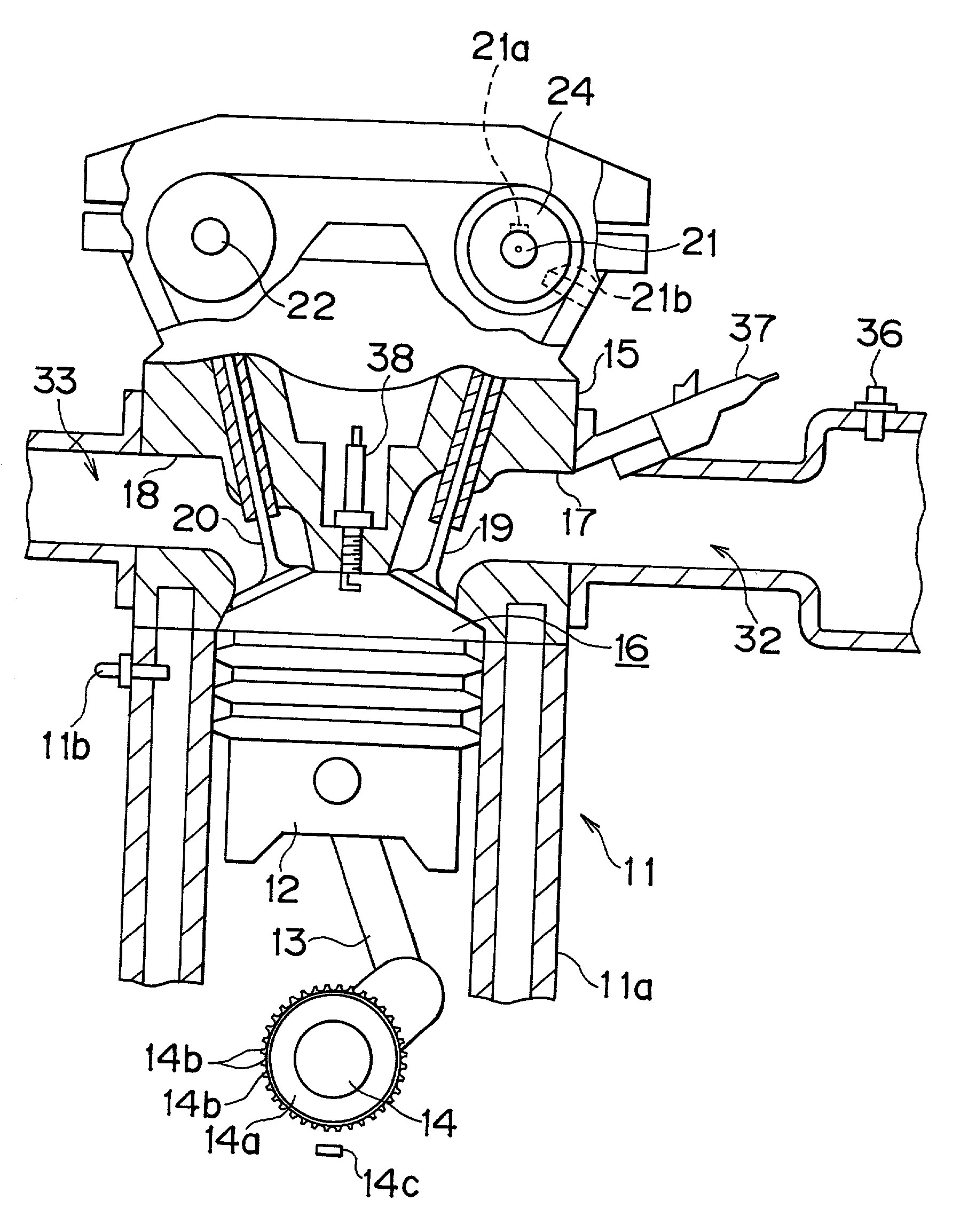
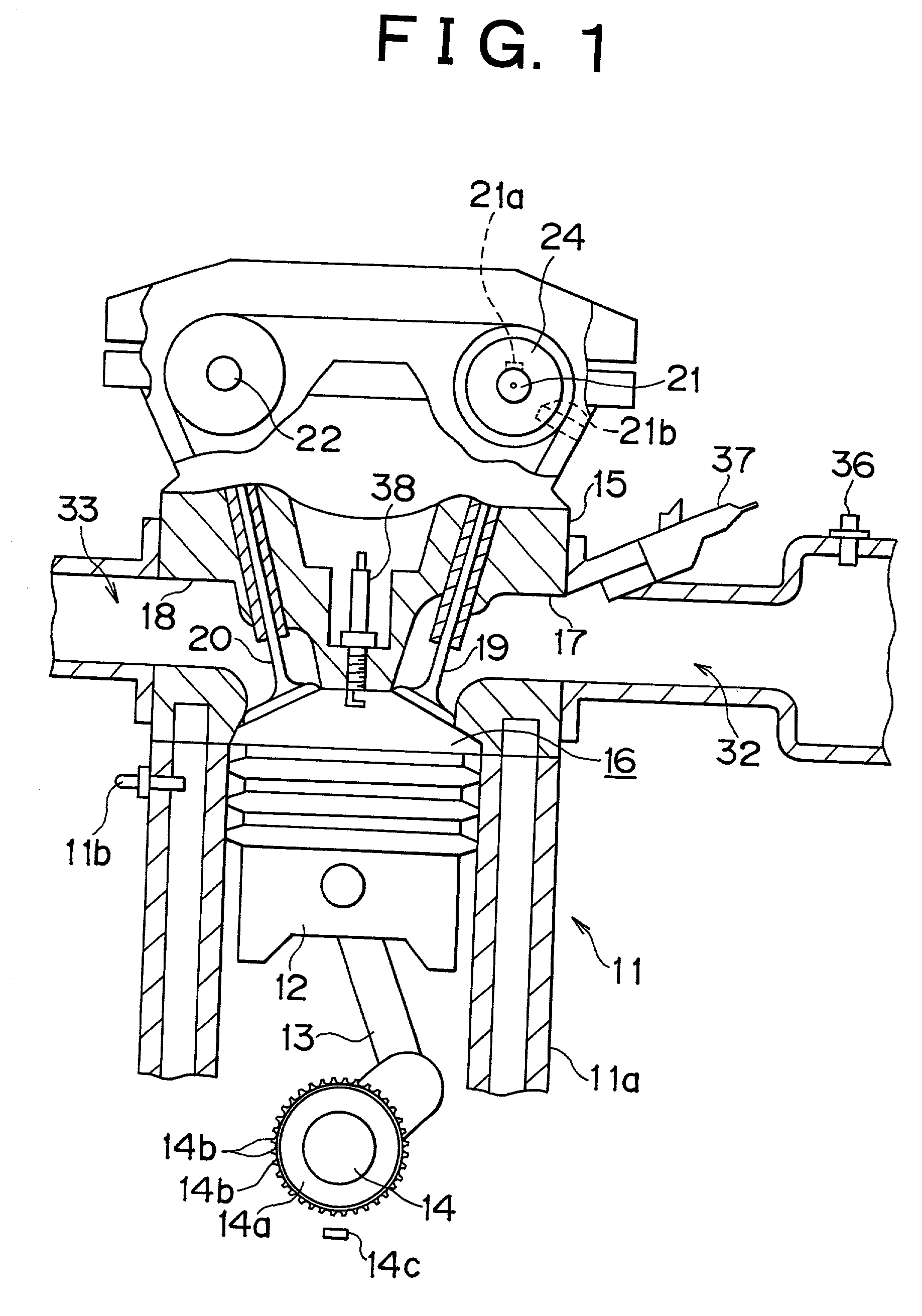
[0059] the invention when applied to an automobile engine will be described with reference to FIGS. 1 to 9.

[0060] As shown in FIG. 1, a cylinder block 11a of an engine 11 is provided with a total of four pistons 12 (only one of them is shown in FIG. 1) that are received in respective cylinders. The pistons 12 are connected to a crankshaft 14, that is, an output shaft of the engine 11, via corresponding connecting rods 13. Reciprocating movements of each piston 12 are converted into rotation of the crankshaft 14 by each connecting rod 13.

[0061] The crankshaft 14 is provided with a signal rotor 14a. An outer peripheral portion of the signal rotor 14a is provided with a plurality of protrusions 14b that are formed at each predetermined angle about an axis of the crankshaft 14. A crank position sensor 14c is provided at one side of the signal rotor 14a. As the protrusions 14b of the signal rotor 14a sequentially pass the crank position sensor 14c during rotation of the crankshaft 14, th...

second embodiment

[0167] Second Embodiment

[0168] A second embodiment of the invention will next be described with reference to FIGS. 10 and 11. In this embodiment, when the deviation of the actual advance amount .theta.rk from the target advance amount .theta.t continues to be less than the predetermined value a, the holding duty ratio H is stored as a holding duty ratio Hv1 or as a holding duty ratio Hv2 depending upon whether the bias force of the thrust mechanisms 53 acts on the intake camshaft 21, unlike the first embodiment in which a value obtained by removing the influence of the bias force from the holding duty ratio H is simply stored as a holding duty ratio Hv. Furthermore, in order to calculate a holding duty ratio H for calculation of a duty ratio D in the second embodiment, a selected one of the holding duty ratios Hv1 and Hv2 is used depending upon whether the bias force is currently acting on the intake camshaft, instead of correcting the holding duty ratio Hv in view of the bias force...


PUM


Abstract

A valve timing control apparatus of an internal combustion engine that includes a biasing device that applies bias force to a camshaft of intake or exhaust valves so as to bring the valve timing of the engine into a predetermined state when the valve timing is in a predetermined range, for example, when the valve timing is on the retard side of the engine start valve timing with which the engine is started is controlled by a controller that controls the valve timing in view of the bias force of the biasing device.

Description

INCORPORATION BY REFERENCE[0001] The disclosures of Japanese Patent Applications No. 2000-055558 filed on Mar. 1, 2000 and No. 2001-001553 filed on Jan. 9, 2001 each including the specification, drawings and abstract are incorporated by reference in its entirety.[0002] 1. Field of the Invention[0003] The invention relates to a valve timing control apparatus and method of an internal combustion engine.[0004] 2. Description of Related Art[0005] Conventional internal combustion engines, such as engines installed on vehicles, are provided with a valve timing apparatus that controls the valve timing of the engine in an attempt to improve the output performance and enhance the emission quality, for example. Such a valve timing control apparatus includes a variable valve timing mechanism that is actuated by hydraulic pressure to change the valve timing of the engine. The variable valve timing mechanism includes, for example, a movable member connected to an intake camshaft of the engine, a...

Claims


Application Information

Patent Timeline
IPC IPC(8): F01L1/34F01L1/344F02D13/02
CPCF01L1/34F01L1/344F02D13/02F01L2001/34426F01L2001/34483F02D2041/001Y02T10/18F01L3/20F01L2001/0537F01L2001/34463F01L2001/34473F01L2250/02F01L2800/03F01L2800/05F01L2820/041F01L2820/042F01L2820/044F02D13/0234F02D2013/0292Y02T10/12
Inventor MORIYA, YOSHIHITOKAWASE, HIROYUKINAGAOSA, HIDEO
Owner TOYOTA JIDOSHA KK
Why Eureka
Try Eureka