Apparatus for and method of operating a furnace blower to evaporate condensate within an exhaust flue

a technology of condensate and furnace, which is applied in the direction of machines/engines, liquid fuel engines, lighting and heating apparatus, etc., can solve the problems of shortening the life of the blower motor, increasing the temperature in the vestibule, and degrading the performance of furnace components located in the vestibule, so as to reduce the noise associated with the blower, reduce the noise, and reduce the cost

Inactive Publication Date: 2002-02-07
JAKEL
View PDF0 Cites 35 Cited by
  • Summary
  • Abstract
  • Description
  • Claims
  • Application Information

AI Technical Summary

Benefits of technology

0018] The blower of the present invention eliminates the need for an auxiliary fan and allows for the blower to be more compact and streamlined. The blower of the present invention has no external rotating equipment, and the safety concerns and costs incident with the auxiliary rotating fan are obviated. The blower motor of the present invention allows the use of a lower cost blower motor while reducing the noise associated with the blower. When installed in the furnace, the blower of the present invention provides a cooler vestibule and therefore cooler environment for the furnace electronic controls. The blower of the present invention also cools the exhaust stream from the furnace so as to lower overall operating temperatures of the furnace.
0019] Included with the present invention is an appliance control, in the preferred embodiment a furnace control, that may be set to allow for a running of the blower motor for a pre-selected time after each combustion cycle to continue to provide dilution air into the vent and chimney to dry it out. Test data have been obtained using the VENT II program indicating that perhaps as short as a 3 minute run time would provide the desired effect for a typical installation for a 80.5 percent appliance. This provides not only a simple and elegant solution to allow for the retrofit of an appliance using a fan assisted combustion system (FACS) for an older design and less efficient draft appliance, but at less cost and greater effectiveness than with the draft hood solution of the prior art.

Problems solved by technology

During operation of the furnace, temperatures in the vestibule increase and tend to degrade performance of furnace components located in the vestibule.
The elevated temperature within the vestibule tends to shorten the life of the blower motor, and electronics and controls located within the vestibule.
First, the use of an auxiliary fan on the blower motor increases the size and / or height of the motor assembly, thereby preventing the streamlining of the motor assembly and reduction of the space reserved for the blower in the furnace.
The guard and the fan itself also add cost to the blower motor.
The blower motor with an auxiliary fan generates additional noise.
Because the motor operates in the vestibule at higher temperatures, the motor capacity must again be increased, which adds cost to the blower.
While this improvement was highly desirable from an efficiency standpoint, it created new problems with respect to determining and implementing the proper size of flue pipes needed to ensure that the chimney remained dry as the furnace operated.
While a chimney kit does provide a solution enabling replacement of an older design draft furnace with an updated furnace having a combustion blower with minimal reconfiguring of the flue pipes, it does have several drawbacks including its expense and installation cost.
However, these installations have to deal with the same "wet" chimney concerns, and retrofit installations, or replacement installations, must also find a way to prevent a wet chimney.

Method used


Image

  • Apparatus for and method of operating a furnace blower to evaporate condensate within an exhaust flue
  • Apparatus for and method of operating a furnace blower to evaporate condensate within an exhaust flue
  • Apparatus for and method of operating a furnace blower to evaporate condensate within an exhaust flue

Examples


Embodiment Construction

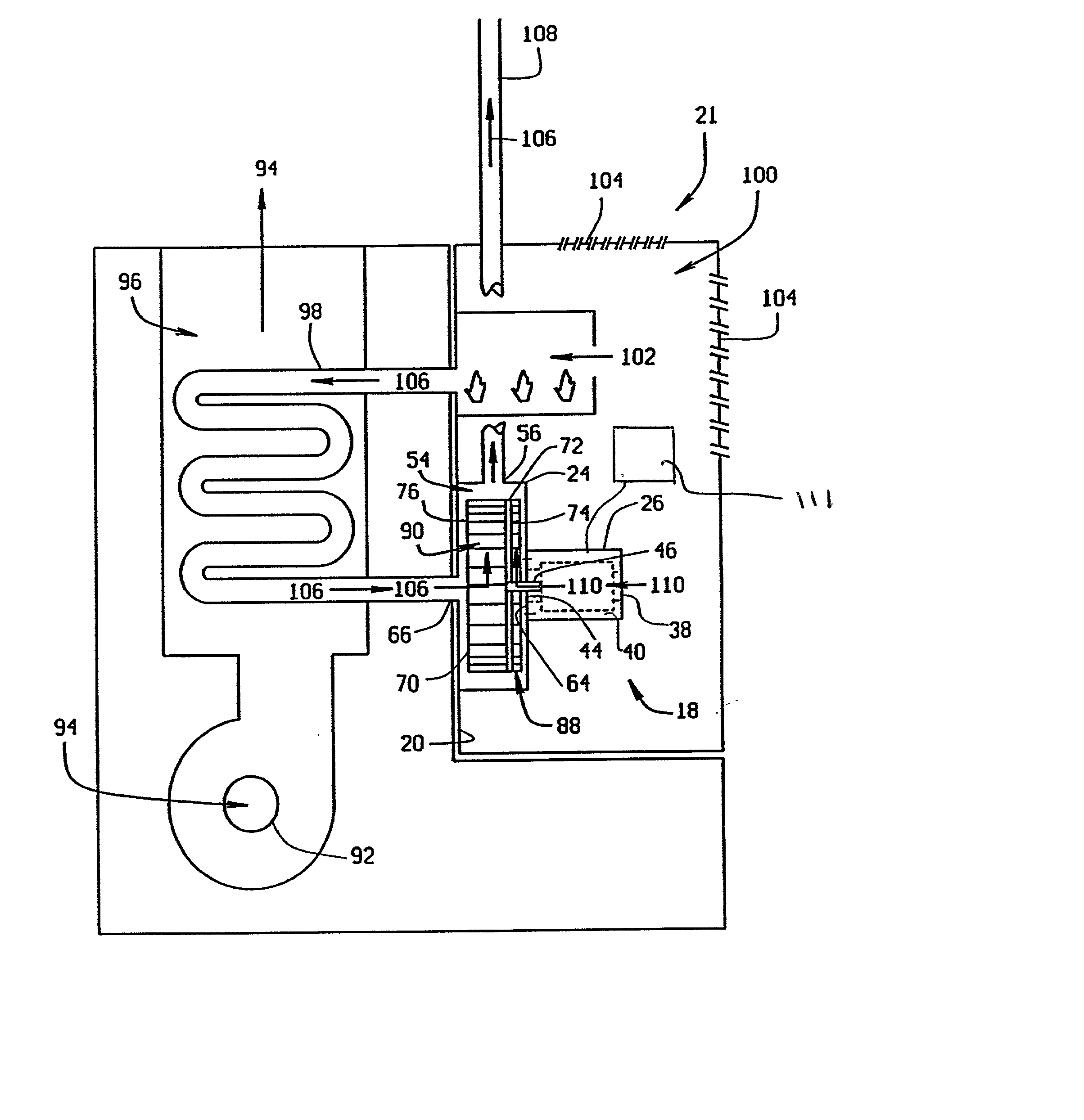
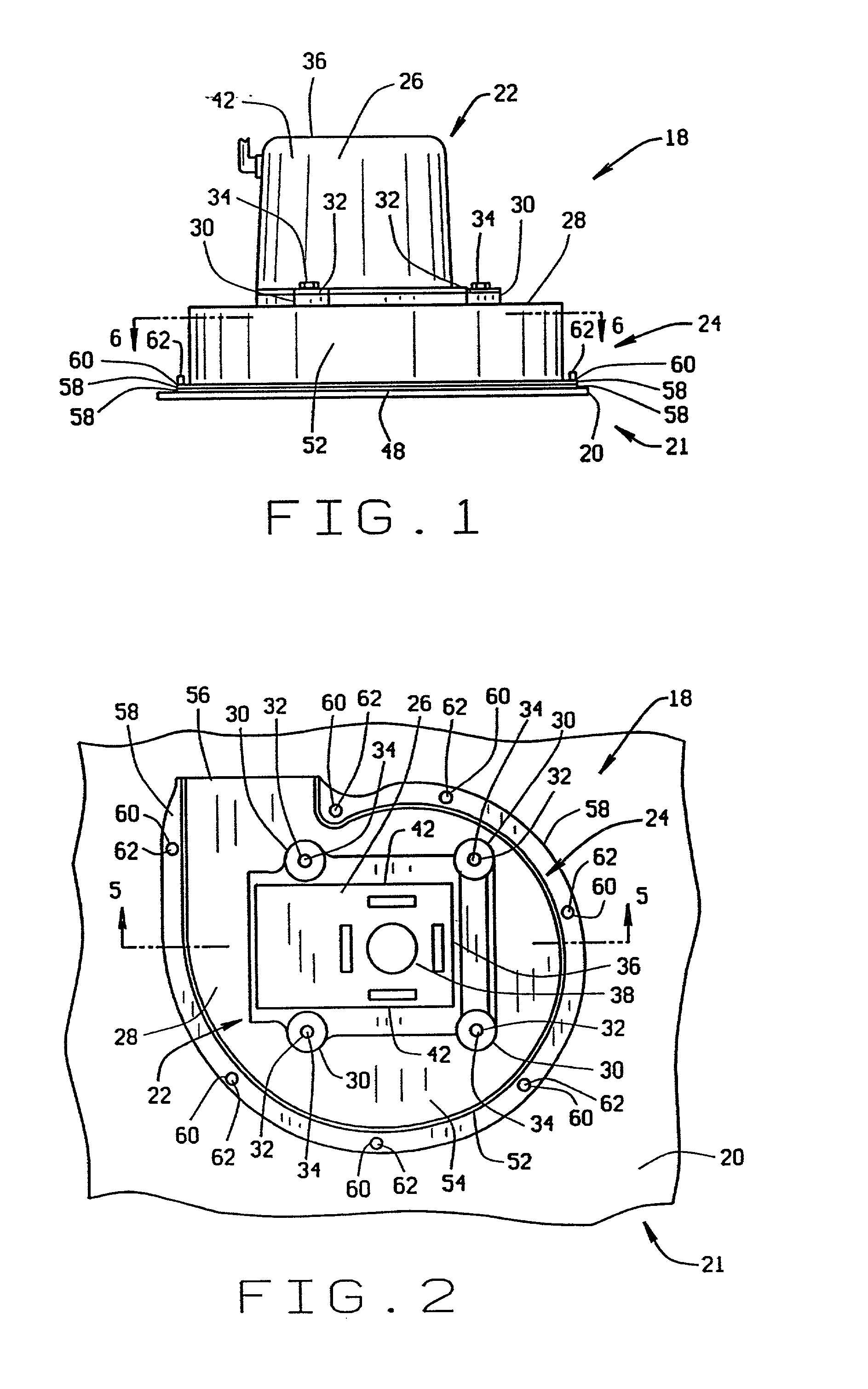
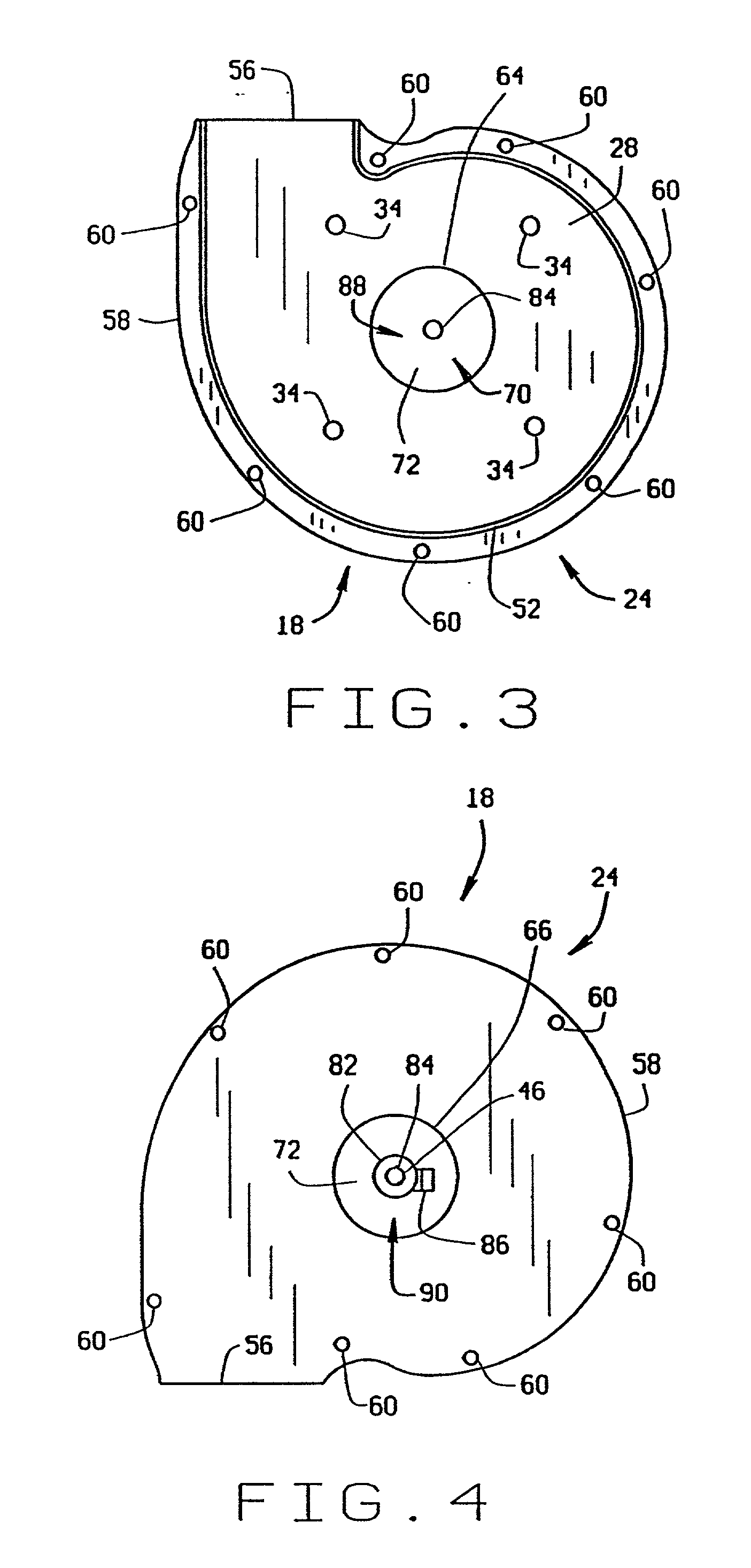
[0031] FIGS. 1-6 provide details of the furnace blower 18 of the present invention. The blower 18 is positioned on a blower mounting surface 20 in a furnace 21 and includes a blower motor 22 and a blower housing 24. The blower motor 22 is preferably positioned on top of the blower housing 24 and contained within a motor casing 26. However, the motor 22 and blower housing 24 could have other relative positions. The motor casing 26 is supported on a first side wall 28 of the blower housing 24 by mounting feet 30 extending outward from the motor casing 26. The mounting feet 30 preferably have mounting holes 32, and mechanical fasteners 34 are directed through the mounting holes 32 to secure the motor casing 26 to the first side wall 28 of the blower housing 24.

[0032] As shown in FIG. 2, on a top side 36 of the motor 22 opposite the top, first side wall 28 of the blower housing 24, the motor casing 26 preferably has at least one vent hole 38 through the motor casing 26 that leads into a...


PUM


Abstract

A blower for a furnace is provided where the blower has an impeller that is configured to create a primary air flow of combustion air into the blower housing and a secondary air flow of cooling air through the blower motor. The primary air flow of combustion air into the furnace generates hot exhaust gases for a heat exchanger in the furnace. The secondary air flow cools the blower motor. The secondary air flow is mixed with the hot exhaust gases in the blower housing and cools the exhaust gases before being discharged from the blower housing. A control operates the blower for a time period after each combustion cycle to introduce ambient air into the exhaust flue and chimney to ensure the evaporation of any condensate forming from the products of combustion contained in the exhaust. The blower may be a variable or multi-speed motor so that a different motor speed may be used for combustion than for the run time after combustion.

Description

[0001] This application is a continuation-in-part of U.S. Ser. No. 09 / 1631,319 filed Aug. 3, 2000.[0002] 1. Field of the Invention[0003] This invention relates generally to a draft inducing blower in a furnace, and, more particularly, the invention pertains to an improvement in the blower design that provides not only for internal cooling for a motor that drives the blower but also a control that runs the blower motor for a period of time after a combustion cycle to ensure that any condensate that collects in the exhaust flue including the chimney will evaporate.[0004] 2. Description of the related Art[0005] Blowers to which the present invention is directed are common in the art. Generally, these blowers are located downstream of a combustion chamber or combustion tubes in the furnace, depending upon the style of furnace. The blower induces combustion air to be drawn into the combustion chamber or combustion tubes, where the combustion air is mixed with fuel and ignited to generate...

Claims


Application Information

Patent Timeline
Patent Type & Authority Applications(United States)
IPC IPC(8): F04D25/08F23L17/00F24H3/06
CPCF04D25/082F23L17/005F24H3/065F04D29/5806
Inventor GATLEY, WILLIAM STUART JR.HALGASH, LINDA M.
Owner JAKEL
Why Eureka
Try Eureka